14 PowerEdge R630 Technical Guide
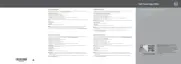
Figure 5 shows the R630 back panel of the 8-drive bay chassis with 3 PCIe slots. Features on the
back panel include the system identification light and button, iDRAC8 Enterprise port (activated only
when iDRAC8 Enterprise is installed), serial connector, video connector, USB connectors, Ethernet
connectors and power supplies.
Figure 5. Back view
Figure 6 is an internal view of the R630 24-drive bay system including fans, DIMMs, power supplies,
system board and hard drive bays.
Figure 6. 24-drive 1.8” bay chassis internal view
For additional system views, see the
Dell PowerEdge R630 Owner’s Manual
on
Dell.com/Support/Manuals.

 Loading...