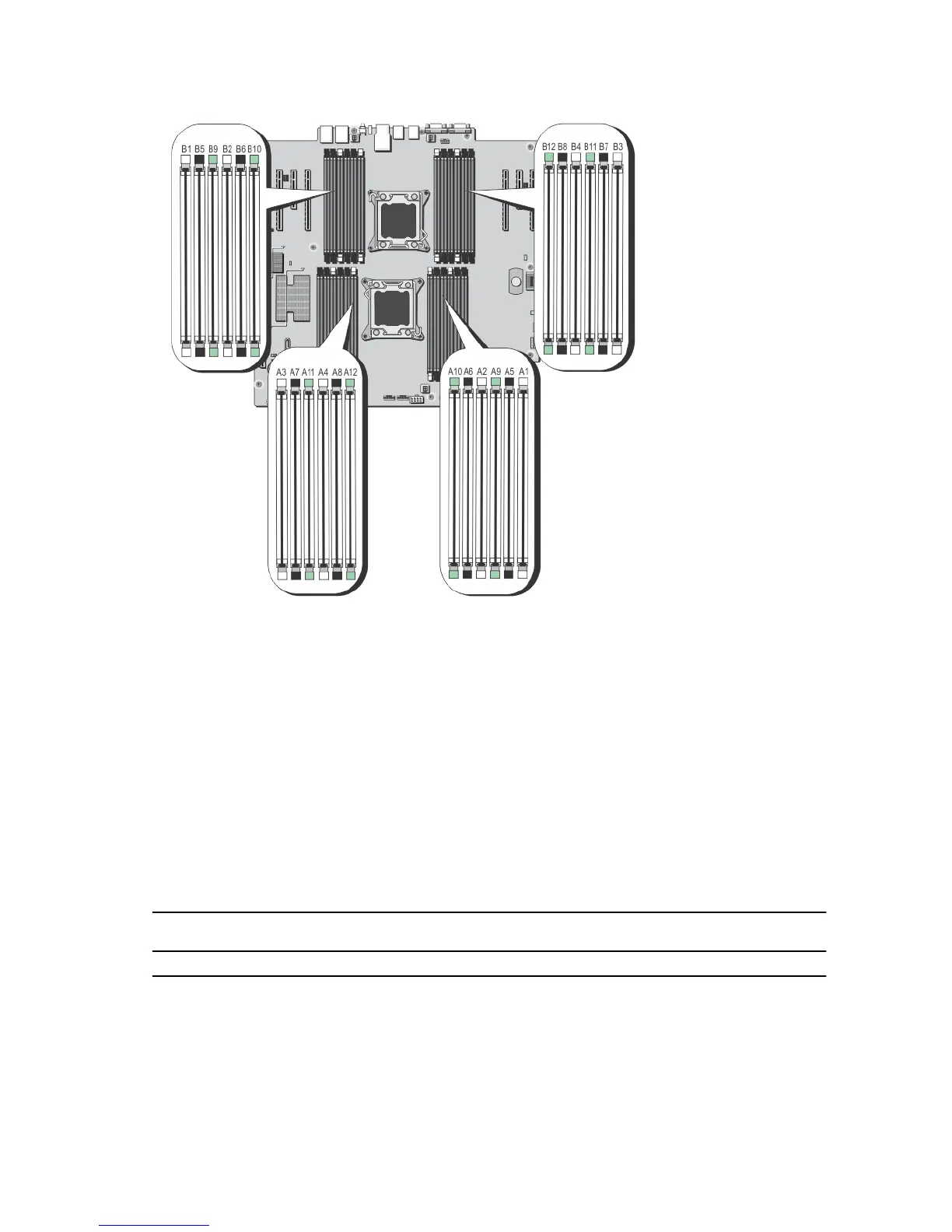
Figure 14. Memory Socket Locations
Memory channels are organized as follows:
Processor 1 channel 0: slots A1, A5, and A9
channel 1: slots A2, A6, and A10
channel 2: slots A3, A7, and A11
channel 3: slots A4, A8, and A12
Processor 2 channel 0: slots B1, B5, and B9
channel 1: slots B2, B6, and B10
channel 2: slots B3, B7, and B11
channel 3: slots B4, B8, and B12
The following table shows the memory populations and operating frequencies for the supported configurations.
DIMM Type DIMMs Populated/
Channel
Operating Frequency (in MT/s) Maximum DIMM Rank/
Channel
1.5 V 1.35 V
UDIMM ECC 1 1333, 1066, and 800 1066 and 800 Dual rank
2 1333, 1066, and 800 1066 and 800 Dual rank
43