Dell
PowerEdge T710 Technical Guide 47
door panel and the front face of the EIA flange for the front door to close with the 11G server bezel
installed.
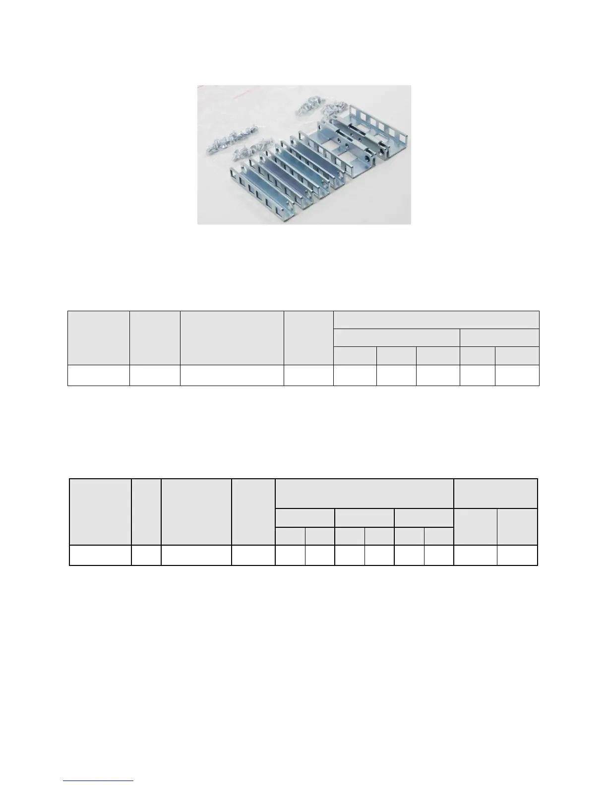
2U Threaded Rack Adapter Brackets Kit Figure 10.
Below is a summary of the rack types supported by the T710 rails. Note that mounting in 2-post racks
is not supported.
Supported Racks Table 19.
*Requires the 2U Threaded Rack Adapter Brackets Kit (Dell part number PKCR1)
Other factors to consider when deploying the T710 include the spacing between the front and rear
mounting flanges of the rack, the type and location of any equipment mounted in the back of the
rack such as power distribution units (PDUs), and the overall depth of the rack.
Rail Adjustability Ranges and Depth Table 20.
Rail Adjustability Range
(mm)
The adjustment range of the rails is a function of the type of rack in which they are being mounted.
The min-max values listed in Table 20 represent the allowable distance between the front and rear
mounting flanges in the rack. Rail depth represents the minimum depth of the rail as measured from
the rack front mounting flanges when the rail rear bracket is positioned all the way forward.
14.3 Cable Management Arm (CMA)
The optional cable management arm (CMA) for the T710 organizes and secures the cords and cables
exiting the back of the server and unfolds to allow the server to extend out of the rack without
having to detach the cables.
Some key features of the T710 CMA include:

 Loading...


