Item Name Icon Description
– Slots for optional front-end connectivity – Fibre
Channel and iSCSI I/O cards
– Slots for optional back-end connectivity – SAS I/O
cards
• SAS expansion ports – Two 12 Gbps SAS ports
• USB port – Single USB 2.0 port
• MGMT port – Embedded Ethernet port that is typically
used for system management
• Serial port – Micro-USB serial port used for initial
configuration and support-only functions
3 Power switch (2) — Controls power for the storage system. Each PSU has one
switch.
4 Power supply/
cooling fan module
LED handle
—
The handle of the PSU indicates the DC power status of the
PSU and the fans.
• Not lit – No power
• Solid green – PSU has valid power source and is
operational.
• Blinking amber – Error condition in a PSU
• Blinking green – Firmware is being updated.
• Blinking green then off – Power supply mismatch
5 Power socket (2) — Accepts the following standard computer power cords:
• IEC320-C13 for deployments worldwide
• IEC60320-C19 for deployments in Japan
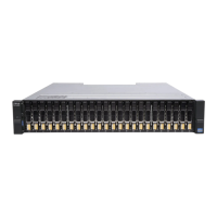
SC7020 Storage System Drives
The SC7020 storage system supports Dell Enterprise hard disk drives (HDDs) and Dell Enterprise solid-
state drives (eSSDs) only.
The drives in the SC7020 storage system are installed horizontally. The indicators on the drives provide
status and activity information.
Figure 3. SC7020 Storage System Drive Indicators
Item Control/Feature Indicator Code
1 Drive activity
indicator
• Blinking green – Drive has I/O activity
• Steady green – Drive is detected and has no faults
2 Drive status
indicator
• Steady green – Normal operation
• Blinking green – A command was sent by Dell Storage Manager to
the disk to make the LED blink so that users can identify the disk in
the rack.
• Blinking amber – Hardware or firmware fault
SC7020 Storage System Hardware
7