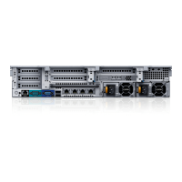
Item Indicator, button, or
connector
Icon Description
1 System identification
button
Used to locate a particular system within a rack.
When a System ID button on the front or back
panel is pressed, the front LCD panel and the back
system status indicator flash until one of the
buttons is pressed again.
• Press to toggle the system ID on and off.
• If the system stops responding during POST,
press and hold the system ID button for more
than five seconds to enter BIOS progress mode.
2 System identification
connector
Connects the optional system status indicator
assembly through the optional cable management
arm.
3 iDRAC8 Enterprise port Dedicated management port.
4 Low-profile IO card slots
(3)
― Ports are numbered from left to right.
5 Serial connector Connects a serial device to the system.
6 Video connector Connects a VGA display to the system.
7 USB connector (2) Connects USB devices to the system. The ports are
USB 3.0-compliant.
8 Full-height IO card slots
(3)
― Ports are numbered from right to left.
9 Ethernet connectors Connects the storage controller to the Ethernet
switch and to other storage controllers in the rack.
The ports function as follows:
• IPC 1: 10Gb (Connect to second storage
controller for IPC).
• MGMT 0: 1GbE (Connects to the Ethernet
switch for system login, email, alerts, SNMP
traps, diagnostic data, and access for software).
NOTE: IPC 3 and MGMT 2 are not used.
10 Power supply unit (PSU1) ― 1100 W, 100–240 V AC, autoranging, 50/60 Hz
11 Cache card ― Improves the performance of the storage system
by temporarily storing data before it is written to
disk.
12 Power supply unit
(PSU2)
― 1100 W, 100–240 V AC, autoranging, 50/60 Hz
8
About the SC9000