Steps
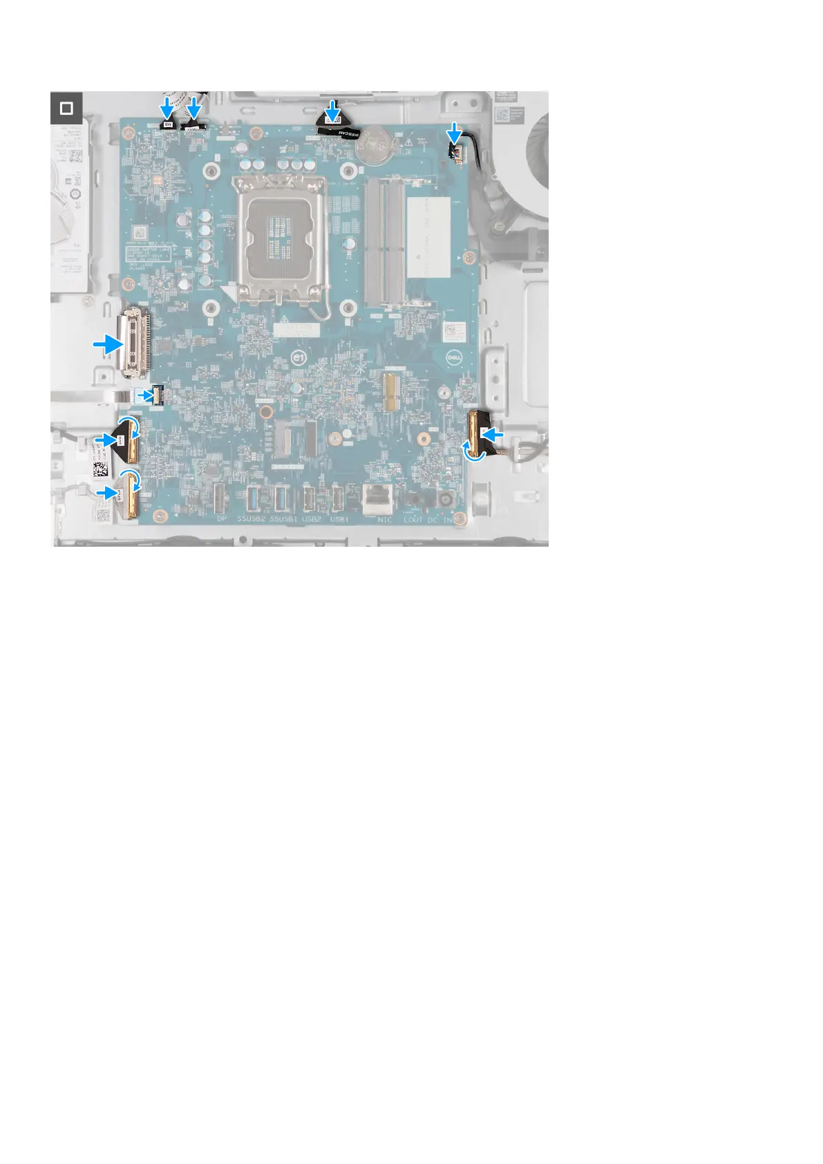
1. Gently place the system board on the display-assembly base.
2. Align the screw holes on the system board with the screw holes on the display-assembly base.
3. Replace the seven screws (M3x5) that secure the system board to the display-assembly base.
4. Replace the screw (M3x12) that secures the system board to the display-assembly base.
5. Connect the touchscreen cable (TOUCH) to the system board.
6. Connect the display-backlight cable (LCB BACKLIGHT) to the system board.
7. Connect the camera cable (WEBCAM) to the system board.
8. Connect the fan cable (FAN CPU) to the system board.
9. Connect the audio cable (MB-AUDIO) to the system board and close the latch.
10. Connect the high-speed cable (MB-HS) to the system board and close the latch.
11. Connect the power cable (MB-PWR) to the system board and close the latch.
12. Connect the display cable (CVDS) to the system board.
13. Connect the hard-drive cable (SATA 1) to the system board and close the latch.
Next steps
1. Install the processor.
2. Install the heat sink.
3. Install the wireless card.
4. Install the M.2 2230 solid-state drive or the M.2 2230 solid-state drive, whichever applicable.
5. Install the I/O bracket.
6. Install the bottom cover.
7. Install the I/O cover.
8. Install the system-board shield.
9. Install the memory.
10. Install the back cover.
146
Removal and installation procedures for Energy Efficient processors