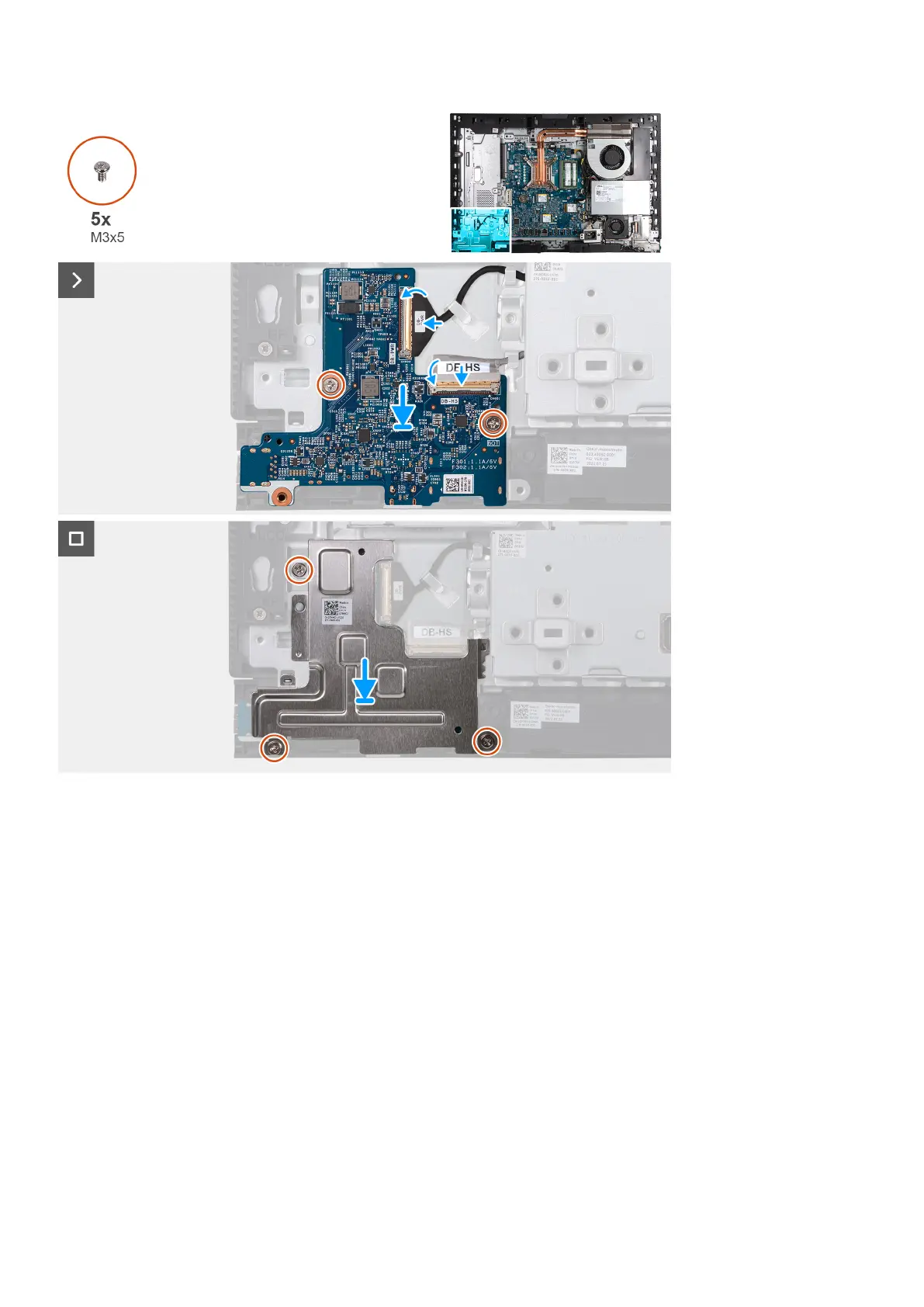
Steps
1. Place the power-button and I/O board on the display-assembly base.
2. Align the screw holes on the power-button and I/O board with the screw holes on the display-assembly base.
3. Replace the two screws (M3x5) that secure the power-button and I/O board to the display-assembly base.
4. Connect the power cable (DB-PWR) to the power-button and I/O board and close the latch.
5. Connect the high-speed cable (DB-PWR) to the power-button and I/O board and close the latch.
6. Place the power-button and I/O board shield on the display-assembly base.
7. Align the screw holes on the power-button and I/O board shield with the screw holes on the display-assembly base.
8. Replace the three screws (M3x5) that secure the power-button and I/O board shield to the display-assembly base.
Next steps
1. Install the I/O bracket.
2. Install the bottom cover.
3. Install the I/O cover.
4. Install the system-board shield.
5. Install the back cover.
6. Install the stand.
7. Follow the procedure in After working inside your computer.
Removal and installation procedures for High Performance processors
99