Do you have a question about the Delta Controls DNT-T103 and is the answer not in the manual?
| Device Type | Thermostat |
|---|---|
| Communication Protocol | BACnet MS/TP |
| Type | Digital |
| Operating Temperature | 0 to 50°C (32 to 122°F) |
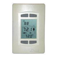
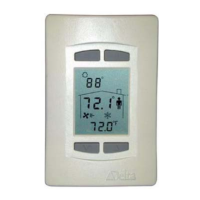
| Display | LCD |
| Accuracy | ±1°F (±0.5°C) |
| Mounting | Wall mount |
Explains BACstat MS/TP network speed and configuration.
Details flash loadable firmware and its support by Flashloader V3.33.
Guides BACstat configuration via keypad, including PIN access and button functions.
Lists and describes menu items for BACstat setup, including applications and parameters.
Details MS/TP specific settings such as Device Address, Baud Rate, and DNA.
Explains how to access and navigate the Service Tool Mode without a PIN.
Details the main menu and Air Balancer menu options available in Service Tool Mode.
Explains input calibration for MS/TP connections using local AI objects or Service Tool Menu.
States that only locally resident scale ranges may be used on MS/TP.
Lists predefined, non-creatable objects in BACstat II products accessible over MS/TP.
Describes event codes and counts for notable events like resets and communication failures.
Provides an overview of BACstat control applications and their functions.
Explains algorithm modes (Unoccupied, Occupied, Lockouts) and their effect on control.
Describes the NONE (MUX) application for remote control of outputs.
Details the VAV application for controlling VAV boxes, including I/O configurations.
Details the VVT application for controlling VVT boxes, including I/O configurations.
Describes the HPU application for controlling Heat Pump Units with reversing valve and fan.
Details the FCU application for controlling Fan Coil Units with fan, including I/O configurations.
Details the Humidity application for simple humidifier control.
Lists and describes output functions like MUX, Heating, Cooling, Fan, Compressor, Reversing Valve.
Lists and describes output types (Binary, PWM, Analog, Flow Damper, Time Proportioned, Tri-State).
Details essential configuration items for BACstats on an MS/TP network via OWS.
Lists configurable BACstat settings via OWS, including Application and Output Configurations.
Lists control settings (Algorithm Mode, Setpoints) that can be set via OWS or GCL+.
Warns against commanding configuration variables on the fly from GCL+ or user commands.
Advises on programming practices for commanding variables to limit network traffic.
Details LINKnet configuration menu items for BACstats.
Explains LINKnet input calibration procedures for BACstats.
Describes objects accessible over the network when BACstats are connected via LINKnet.
Advises on programming practices for commanding variables to limit network traffic.
Shows how to specify temperature units in GCL+ programming for LCD lines 2 and 3.
Explains how to evaluate KeyPress objects in GCL+ for BACstat button presses.