Chapter 3 Connections and Wiring
3-2 Revision January 2011
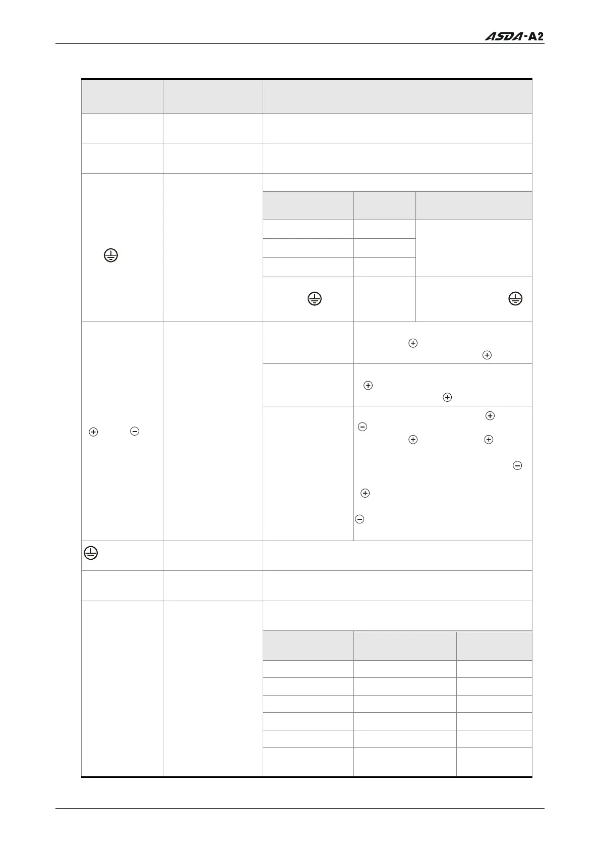
3.1.2 Servo Drive Connectors and Terminals
Terminal
Identification
Terminal
Description
Notes
L1c, L2c
Control circuit
terminal
Used to connect single-phase AC control circuit
power depending on connecting servo drive model.
R, S, T
Main circuit
terminal
Used to connect three-phase AC main circuit power
depending on connecting servo drive model.
Used to connect servo motor
Terminal
Symbol
Wire Color
Description
U Red
V White
W Black
Connecting to three-
phase motor main
circuit cable.
U, V, W
FG (
)
Servo motor
output
FG(
)
Green
Connecting to
ground terminal (
)
of the servo drive.
Internal resistor
Ensure the circuit is closed
between P
and D, and the
circuit is open between P
and C.
External resistor
Connect regenerative resistor to
P
and C, and ensure an open
circuit between P
and D.
P , D, C,
Regenerative
resistor terminal
or braking unit
External braking
unit
Connect braking unit to P
and
, and ensure an open circuit
between P
and D, and P and
C.
(N terminal is built in L
1C
, L
2C
, ,
and R, S, T.)
P
: Connecting to (+) terminal of
V_BUS voltage.
: Connecting to (-) terminal of
V_BUS voltage.
two places
Ground terminal
Used to connect grounding wire of power supply
and servo motor.
CN1
I/O connector
(Optional Part)
Used to connect external controllers. Please refer to
section 3.3 for details.
Used to connect encoder of servo motor. Please
refer to section 3.4 for details.
Terminal
Symbol
Wire Color Pin No.
T+ Blue 5
T- Blue/Black 4
Reserved - -
Reserved - -
+5V Red & Red/White 14, 16
CN2
Encoder
connector
(Optional Part)
GND
Black &
Black/White
13, 15
Call 1(800)985-6929 for Sales
Call 1(800)985-6929 for Sales