Chapter 2 Wiring|DD Series
2-3
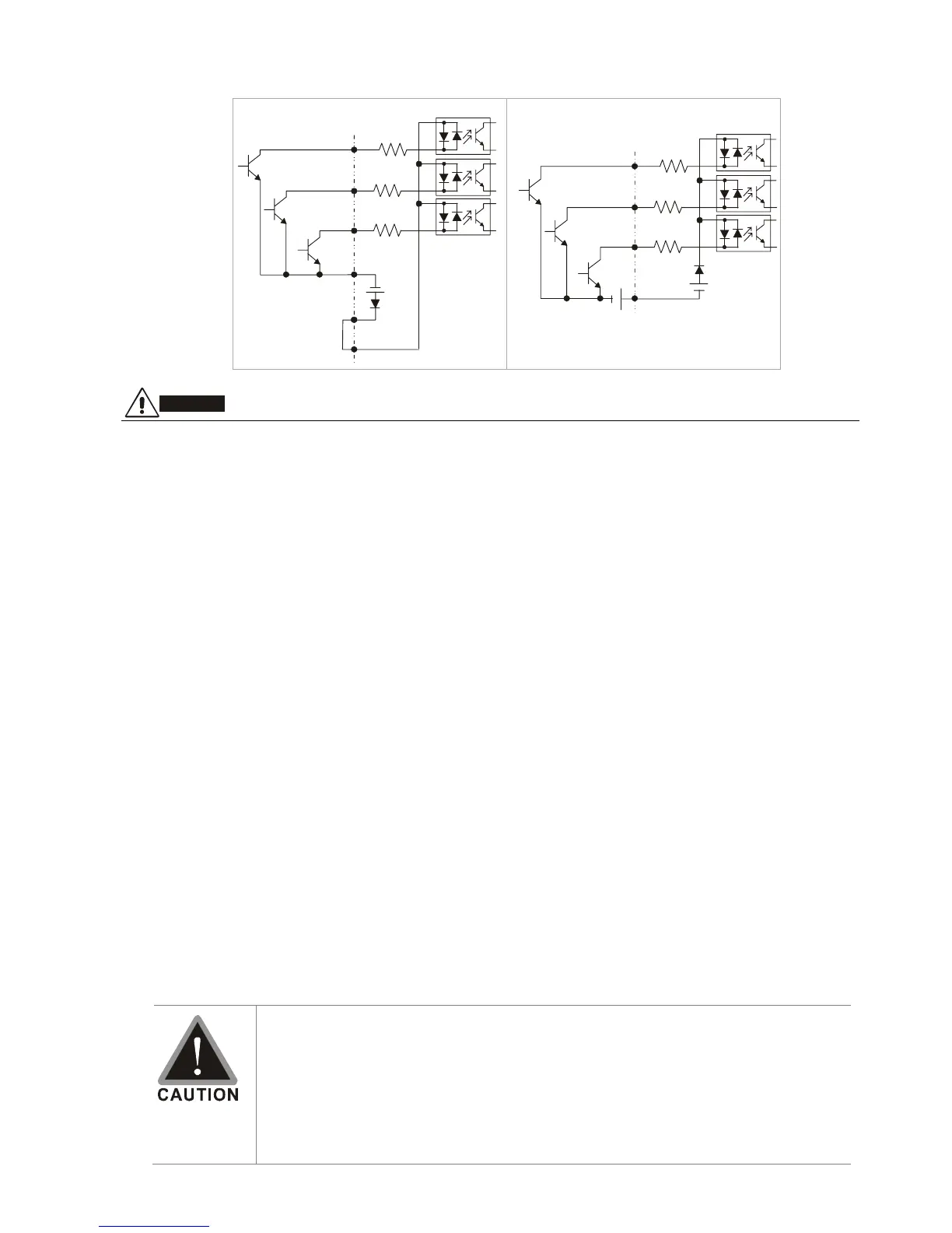
Wiring/Terminals Setting
Used with internal power (+24Vdc)
Used with external power
COM
MI1
+24V
MI2
MI5
~
External +24V power
+
COM
MI1
+24V
MI2
MI5
~
COM
CAUTION!
;
The wiring of main circuit and control circuit should be separated to prevent erroneous actions.
;
Please use shield wire for the control wiring and not to expose the peeled-off net in front of the
terminal.
;
Please use the shield wire or tube for the power wiring and ground the two ends of the shield wire
or tube.
;
Damaged insulation of wiring may cause personal injury or damage to circuits/equipment if it
comes in contact with high voltage.
;
The AC motor drive, motor and wiring may cause interference. To prevent the equipment damage,
please take care of the erroneous actions of the surrounding sensors and the equipment.
;
When the AC drive output terminals U/T1, V/T2, and W/T3 are connected to the motor terminals
U/T1, V/T2, and W/T3, respectively. To permanently reverse the direction of motor rotation, switch
over any of the two motor leads.
;
With long motor cables, high capacitive switching current peaks can cause over-current, high
leakage current or lower current readout accuracy. For usage of long motor cables use an AC
output reactor.
;
The AC motor drive, electric welding machine and the greater horsepower motor should be
grounded separately.
;
Use ground leads that comply with local regulations and keep them as short as possible.
;
No braking resistor is built in the VFD-DD series, it can install braking resistor for those occasions
that use higher load inertia or frequent start/stop. Refer to Appendix B for details.
;
Multiple VFD-DD units can be installed in one location. All the units should be grounded directly to
a common ground terminal, as shown in the figure below. Ensure there are no ground loops.
;
The wiring of main circuit and control circuit should be separated to prevent
erroneous actions.
;
Please use shield wire for the control wiring and not to expose the peeled-off
net in front of the terminal.
;
Please use the shield wire or tube for the power wiring and ground the two
ends of the shield wire or tube.