ES150 DELTA ELEKTRONIKA BV
rev. March 2017 DESCRIPTIONS Page 3 - 3
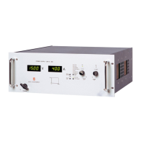
15) PUL SATING LOAD
To avoid over heat ing the out put ca pac i tors, the AC com po nent
of the load cur rent should be lim ited (see fig. 3 - 9).
One method of de creas ing the AC cur rent through the out put ca -
pac i tor is by us ing a large ex ter nal elec tro lytic ca pac i tor in par al -
lel with the load.
Care must be taken so that the ca pac i tor in com bi na tion with the
lead in duc tance will not form a se ries res o nant cir cuit!
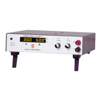
16) IN SU LA TION
For safety the in su la tion of the sep a rat ing com po nents (trans -
form ers) be tween in put and out put is tested at 3750 Vrms dur ing
1 min ute. This is tested be fore as sem bling.
Warn ing! The 3750 Vrms can not be tested af ter wards on the
as sem bled unit be cause the in su la tion be tween the com po nents
on the in put side to the case (like the bridge rec ti fier) is spec i fied
at 2500 Vrms. Since the in su la tion out put - case is low (only 600
VDC) the in su la tion of the pri mary com po nents to case will break
down when 3750 Vrms is ap plied be tween in put and out put
(2500 Vrms + 600 VDC < 3750 Vrms) (see also fig. 3 - 10).
Note: when test ing the in su la tion, take care to charge and dis -
charge the ca pac i tors be tween in put - case and out put - case
slowly (e.g. in one sec ond). This to pevent high peak cur rents,
which could de stroy the power sup ply. Make sure to have dis -
charged the ca pac i tors com pletely be fore us ing it again.
17) RFI SUP PRES SION
Both the in put and out put have RFI fil ters, re sult ing in very low
con ducted RFI to the line and load. Due to the out put fil ter the
out put volt age is very clean, hav ing al most no spikes.
The com bi na tion of RFI fil ters and the closed metal case re sults
in a low ra di ated RFI.
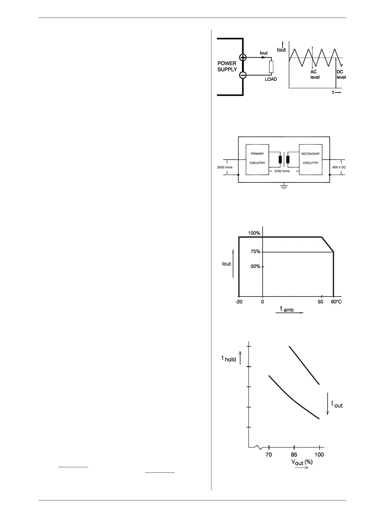
18) OP ER ATING TEMP
At full power the op er at ing tem per a ture range is –20 to +50 °C.
From 50 to 60 °C the out put cur rent has to be de rated lin early to
75 % at 60 °C (see fig. 3 - 11). These tem per a tures hold for nor -
mal use.
19) THER MAL PRO TEC TION
A ther mal switch shuts down the out put in case of in suf fi cient
cool ing. Af ter cool ing down the unit will start work ing again.
20) HOLD - UP TIME
The hold - up time de pends on the load, out put volt age and line
in put volt age. A lighter load or a lower out put volt age re sults in a
lon ger hold - up time (see fig. 3 - 12). The in flu ence of the line in -
put volt age is lim ited be cause of the ac tive PFC.
21) TURN ON DE LAY
The out put volt age is avail able 0.25 sec af ter mains switch on.
22) IN RUSH CUR RENT
The in rush cur rent is lim ited with a 30 Ohm NTC to about 10 A
when the NTC is cold.
23) COOLING
The cool ing is by nat u ral con vec tion, no noisy blow ers are pres -
ent. The unit should have suf fi cient free space to let the air flow
ver ti cally through the unit. A dis tance of min i mum 5 cm around
the unit is rec om mended.
For long life the tem per a ture of the air en ter ing the unit, should
be be low 35 °C
un der nor mal con di tions.
Un der ex treme con di tions it should be be low 50 °C
.
fig. 3 - 9
Pul sat ing load cur rent
fig. 3 - 10
In su la tion test volt ages
fig. 3 - 11
Op er at ing tem per a ture ranges
fig. 3 - 12
Hold-up time vs Vout with Iout as a pa ram e ter
 Loading...