Do you have a question about the Delta Elektronika SM 400-AR-8 and is the answer not in the manual?
| Brand | Delta Elektronika |
|---|---|
| Model | SM 400-AR-8 |
| Category | Power Supply |
| Language | English |
General safety precautions for operation, service, and repair of the equipment.
Evaluation of power supplies to installation category II (Over voltage category II).
Requirements for connecting the unit to the AC power supply mains via a three-conductor cable.
Safety considerations for grounding DC power terminals, including voltage limits.
Warning about touching live parts after disconnecting from mains due to charged capacitors.
Guidelines for connecting the unit to the mains supply permanently or via an industrial plug.
Fuses must only be changed by authorized personnel for continued protection.
Do not use an AC supply exceeding the unit's specified voltage and frequency ratings.
Operating personnel must not remove covers; internal adjustments are for qualified personnel only.
Allowed only by authorized personnel; repairs require return to a service facility.
Safety covers protect against hazardous voltages; follow specific steps for removal and reinstallation.
Warnings regarding unit weight, sharp edges, and mounting restrictions (no wall/ceiling mount).
Airflow is crucial for cooling; hot components and fan openings require caution.
Warning about strong magnetic fields from high currents affecting medical devices like pacemakers.
Specifies usage, ambient temperature, humidity, altitude, and pollution degree for safe operation.
Explains caution symbols for electrical shock and instruction manual references.
Compliance with Canadian safety standards for electrical equipment.
Certification mark indicating compliance with relevant safety standards.
Information on correct disposal and recycling of the product.
Guidelines for responsible disposal and recycling in the European Union.
Describes constant voltage/current modes, autoranging, and output ranges.
Units have a wide AC input voltage range and require single-phase input.
Features active PFC, resulting in a near-sine wave input current with low harmonic distortion.
Consumes very little power in standby, allowing AC input to remain on.
High and constant efficiency across a wide DC output range, meaning low power loss and heat.
Specifies CV-load regulation measured directly on DC power terminals.
Guidance on accurate CC-load regulation, avoiding external voltage sensing.
Low DC output ripple, measured directly on terminals to avoid magnetic fields.
Describes programming voltage/current via external analog voltage, standardized on 5V.
Methods to prevent earth loops and programming errors using isolated sources or optional cards.
Details on using optional controllers for programming and status monitoring via computer.
Outputs provide a 0-5V signal proportional to output current/voltage, buffered and protected.
Describes the +12V output on the programming connector, its current limit, and protection.
Logic outputs (0V/5V) for various statuses like DCF, ACF, OT, LIM, and CC.
Two status relay outputs with change-over contacts connected to CON D.
Explains the functions of DIP switches 1-5 on SW1 for various settings.
Operation of remote shutdown via voltage or relay contact on CON E.
Describes the interlock connector function to enable/disable the unit output.
Discusses rise/fall times for programming, load dependency, and high-speed options.
Recommendations for handling pulsating loads to avoid overheating DC output capacitors.
Details insulation testing between mains in and DC output for safety.
Features RFI filters on mains input and DC output for low conducted RFI and clean output.
Defines the operating temperature range and derating requirements above 50°C.
Explains the thermal switch shutdown and OT status indication.
Discusses hold-up time dependency on load and DC output voltage.
States the DC output voltage availability approximately 0.2 sec after mains switch-on.
Describes the electronically limited inrush current and potential issues with rapid switching.
Explains remote sensing for constant load voltage and its limitations.
Guidelines for connecting units in series for up to 600V total voltage.
Discusses paralleling units without limitations and recommendations for high-speed programming.
Details how the Master/Slave feature forms larger units and connection methods.
Explains voltage and current limits for circuit protection and their setting.
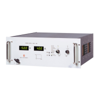
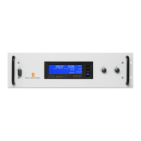
Describes front panel controls, digital encoders, and adjustment options.
Information on the low-noise blower, fan speed dependency, and stacking units.
Provides physical dimensions of the unit.
Advice on humidity and preventing condensation inside the unit.
Operating and storage temperature ranges, and cooling requirements.
Instructions for mounting the unit in a 19-inch rack using support slides.
Step-by-step guide for initial unit setup and operation checks.
Functionality to protect the output from accidental shutdown via button activation.
For units with magnetic encoders, setting the start-up behavior after mains switch-on.
How to set up and use analog programming via the CON E connector.
Using the ISO AMP CARD and CON H for isolated analog programming.
Setting up programming via PSC-488/PSC-232 controllers using CON F/G or CON E.
Compatibility and direct meter driving capability of monitoring outputs.
Details on status output Ø connection and fuse protection.
How to connect and use remote sensing for accurate load voltage.
Explains suitability of power supplies for battery charging applications.
Operation of remote shutdown via CON E or software commands.
Connecting units in series using Master/Slave configuration via RJ45 cables.
Connecting units in parallel using Master/Slave configuration via RJ45 cables.
Recommendations for parallel operation of high-speed programming units.
Connecting complex combinations using a Master/Slave Series Adapter.
Contact information and process for reporting unit defects or seeking repair.
Troubleshooting steps for when the unit has no DC output under manual control.
Diagnosing issues when programming mode yields large errors or incorrect output.
Explains causes of programming offsets, such as earth loops, and solutions.
Troubleshooting steps for when status outputs are not functioning correctly.
Checks for voltage drop and inductance issues in Master/Slave parallel configurations.
Troubleshooting steps for when the DC output voltage exceeds the set value.
Checks for overheating conditions indicated by the OT LED.
Explains the OT LED blinking as a pre-warning for overheating.
Troubleshooting for ACF LED indicating low input voltage or bad connection.
Reasons for DCF LED being on, including CC mode or interrupted interlock.
Indicates Power Sink overload or overheating.
Indicates the Keylock function is activated.
Basic checks for input power and advice to send for repair if no LEDs are active.
States that power supplies need no maintenance or calibration, but cooling must be unobstructed.
Discusses dust buildup, fan function, and thermal protection for the cooling fan.
Precautions for using power supplies in aggressive galvanic environments.
Power supplies are factory calibrated; recalibration only needed in special situations.
How to calibrate digital meters using specific potentiometers.
Calibrations that must be done by qualified personnel only, with warnings.
Declares conformity with EU directives for EMC, LVD, and RoHS.
Declares conformity with relevant UK Statutory Instruments for EMC, Safety, and RoHS.