QUICK START SM15K
6 / 32 DELTA ELEKTRONIKA B.V. rev. January 2021
QUICK START - SM15K-series
3.1
3.1.1 AC POWER TERMINALS (AC-MAINS)
This connector is located at the rear side, marked as CON A.
Use a cable with a diameter of 4 mm
2
for each wire and a sufficient voltage rating for the AC input voltage of the unit.
Use the included 4-pole header with the markings L1, L2, L3, PE for connecting the wire to the unit (see fig. 3 - 1).
The mounting torque for the header terminals is 0.6 Nm.
Always connect the PE terminal to the Protective Earth, no neutral connection is required.
The unit can operate only on a 3 phase grid, with a rated voltage of 380...480VAC.
After installation, connect the pull relief and add the safety cover over the AC terminals.
These terminals are located at the rear side, marked as CON B1 (PLUS) and CON B2 (MINUS), see fig. 3 - 1.
See table 3 - 1 at this page for the correct cable diameter and mounting
torque. Use cables with a sufficient voltage rating for the maximum
output voltage of the unit.
With high output current, use low resistive connections between the
power supply and the load:
- Mount the cable lugs directly on the DC power strips followed by a
washer, a split washer and a nut. Always in this order!
- Never place washers between the lugs and the strips because this
can result in excessive heat!
- Only use nuts and washers supplied with the unit.
The DC power terminals are floating in relation to Protective Earth.
After installation mount the safety cover over the DC power terminals.
Insert a standard RJ45 network cable to the LAN-connector at the rear side, see fig. 3 - 1 and make connection to a
Local Area Network (LAN) to perform a firmware update and use the units' web browser, see next paragraph.
The LAN-connector is at Protective Earth level.
3.1.4 LOAD SENSING, INTERLOCK, USB, INTERFACES, SERIES-PARALLEL, MASTER/SLAVE
Refer to user manual for connecting and using these features and options.
3.2
Switch the unit on by rotating the mains switch on the front panel clockwise.
In the unit menu, check the firmware revision via Menu > System > info > Unit > Version.
Use the V- and A-knob to navigate through the menu.
On a computer, check at if there is new firmware available via: Products > SM15K > Downloads.
If newer, download the firmware package to the computer and connect this to the same LAN as the unit.
In the unit menu, check the IP-address via Menu > Interfaces > LAN > Address*.
On the computer, open the SM15K web interface using an internet browser by entering the IP-address of the unit in the
address bar of the browser.
In the web interface, go to Administration > Firmware.
Select "Choose File" and browse to the downloaded package, enter password and "Start Update".
*Note: when DHCP is enabled, the IP-address can change, for example after a power cycle.
Warning! Never make connections to the Power Inputs, Power Outputs or Sense Connector when the unit is
connected to the mains supply or power outlet! Safety covers are used to cover these in- and outputs.
Carefully read the chapter "Safety Instructions" in this manual before connecting or operating the unit!
Warning! Some components inside the power supply are at AC voltage even when the On/Off switch is in the off
position. Therefore a readily accessible, appropriately rated, disconnect device shall be incorporated external to the
equipment. The power supply shall be connected to the mains supply via a protection device with a rating of
maximum 32A. For example a circuit breaker or fuses etc.
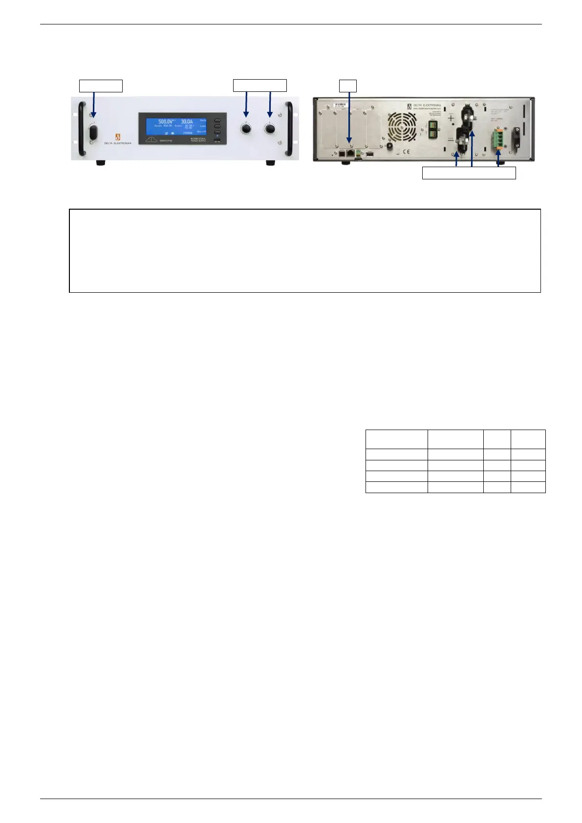
fig 3 - 1 - controls and connections.
table 3 -1
Recommended cable diameters
and mounting torque.
 Loading...

