SM1540-D SM7020-D SM3004-D DELTA ELEKTRONIKA BV
1989 rev. May 2008 DESCRIPTIONS Page 3 - 7
Note: The Ther mal Shut Down and Re mote Shut Down will also cause the
OVP-led to burn and the OVP-status will be high.
When the OVP sta tus output is used as an in dication for ac cidental in ter-
ruption of leads, a de fect in the power supply etc., it is rec ommended to set
the limit well above the working out put voltage to avoid ac cidental lim iting.
The rec om mended OVP set voltages can be read from the following ta ble:
Ex am ple: For a SM7020-D set at 24 V out put voltage it is recommended to
set the OVP on 24 + 3 = 27 V.
30)
PO TEN TI OM E TERS
• Stan dard: - CV and CC po tentiometers with knobs at front panel,
OVP potentiometer with screw driver ad justment at
the front panel.
• Op tion P001: - Screwdriver ad justment for CV, CC and OVP at the
front panel, fig. 3 - 28.
• Op tion P002: - Screwdriver ad justment for CV, CC and OVP at the
rear panel (no po tentiometers at front panel),
fig. 3 - 29.
31)
COOLING
The cool ing is by natural con vection, no noisy blow ers are pres ent. The
unit should have suf ficient free space to let the air flow vertically through the
unit. See fig. 3 - 30. A dis tance of min imum 5 cm around the unit is rec om-
mended.
For long life the temperature of the air en tering the unit, should be be low
35 °C un der nor mal con di tions.
Under ex treme conditions it should be be low
50 °C.
fig. 3 - 27
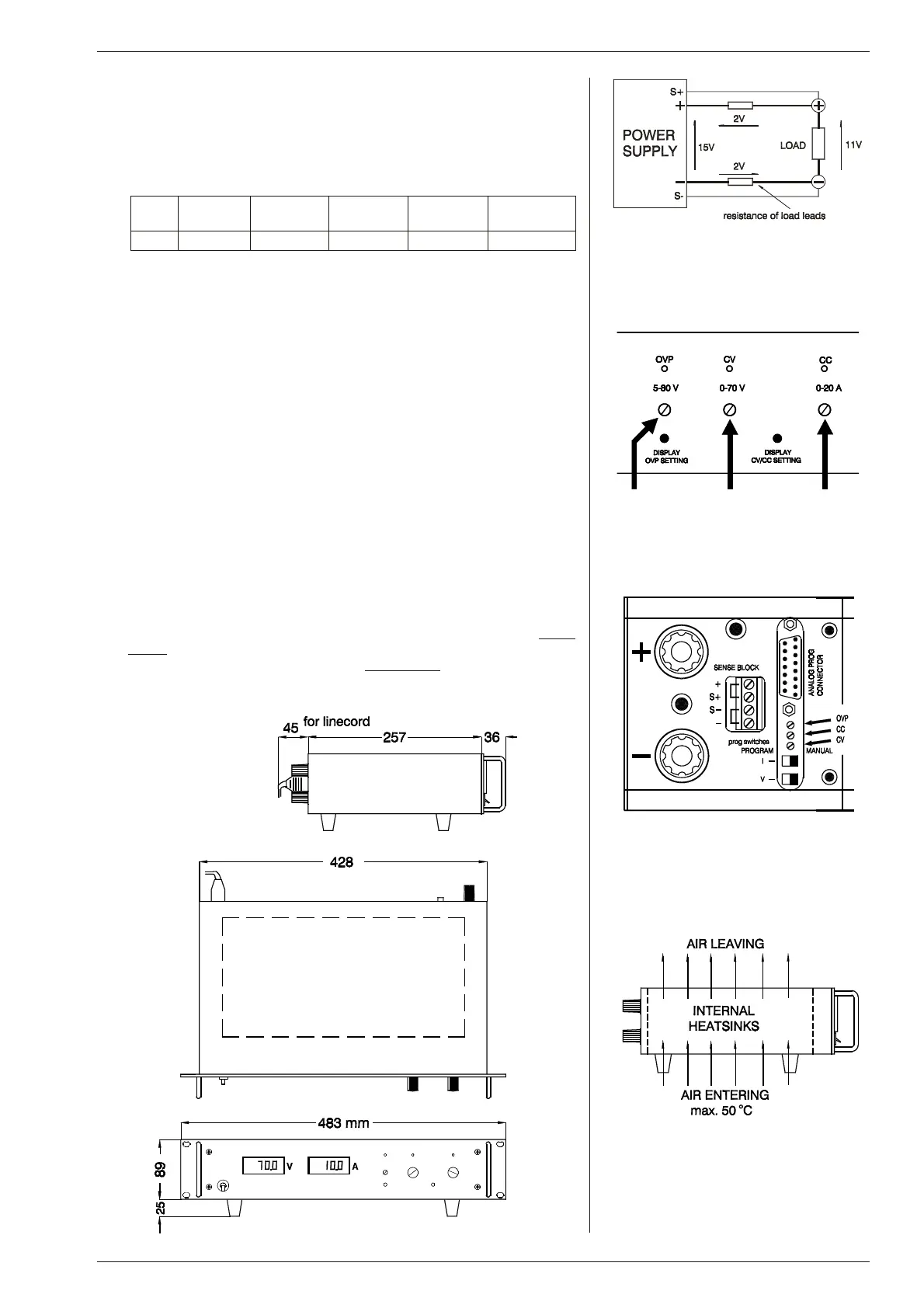
Remote sensing, voltage drop in load
leads sub tracts from max. output
fig. 3 - 28
Op tional screw driver ad just ment
at front panel
fig. 3 - 29
Op tional screw driver ad just ment
at rear panel
fig. 3 - 30
Vertical airflow through the unit
Unit: SM1540-D SM7020-D
range 0 - 35 V
SM7020-D
range 35 - 70 V
SM3004-D
range 0-150 V
SM3004-D
range 150-300 V
Vovp Vout + 2 V Vout + 3 V Vout + 5 V Vout + 10 V Vout + 25 V

 Loading...
