DELTA ELEKTRONIKA BV SM1540-D SM7020-D SM3004-D
Page 3 - 6 DESCRIPTIONS 1989 rev. May 2008
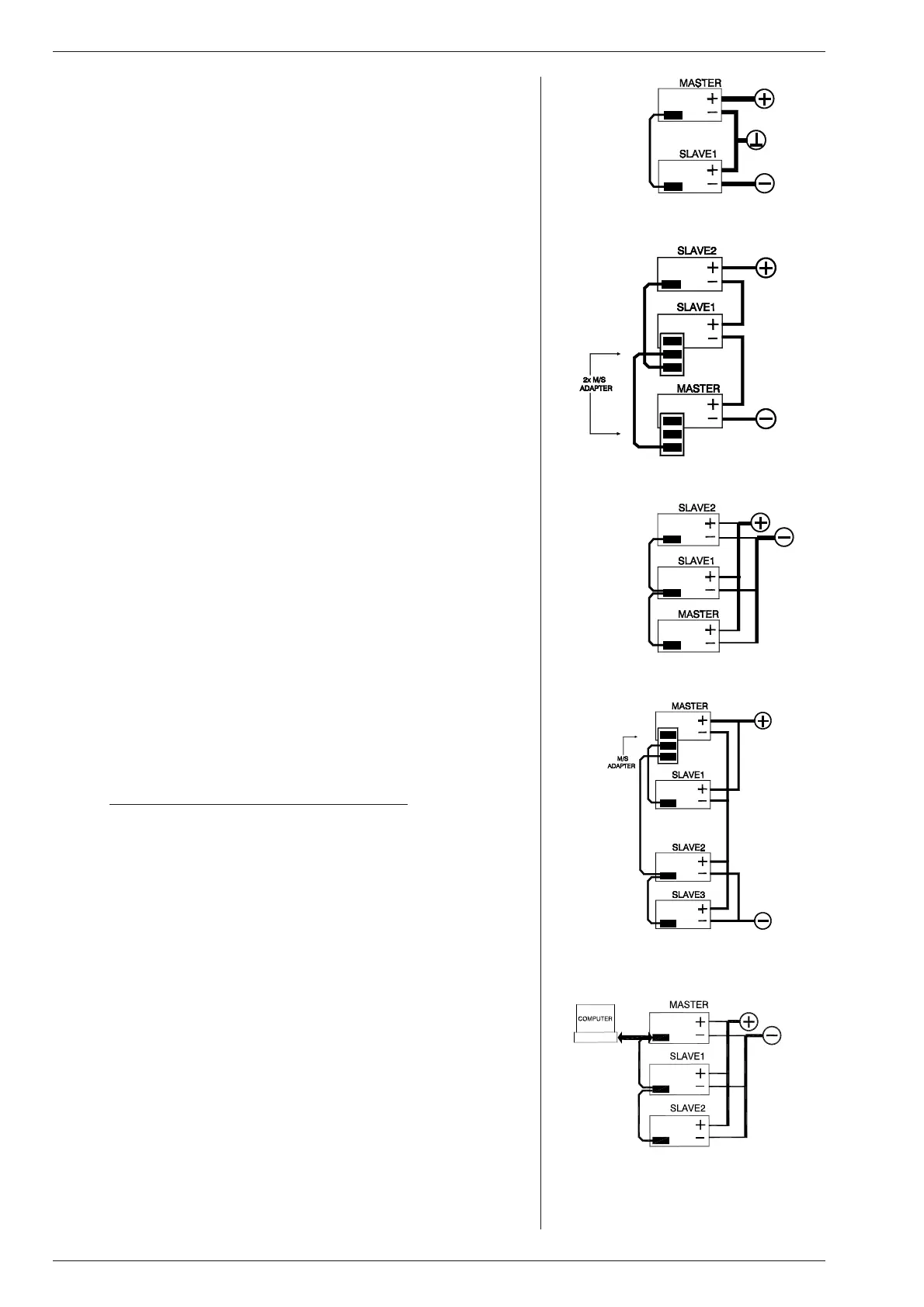
25) SERIES OP ER A TION
Series op eration is al lowed up to 600 V total voltage. The power sup plies
can be con nected in se ries without spe cial pre cautions.
For eas ier con trol, Mas ter / Slave op eration is recommended (fig. 3- 23).
By us ing the Mas ter / Slave se ries fea ture a dual tracking power sup ply
can be made with one unit as master and one as slave.
For se ries op er a tion in com bi na tion with Power Sink op tion, all units must
have a Power Sink built in side oth erwise no power can be ab sorbed.
26)
PAR AL LEL OP ER A TION
Paralleling of the units has no limitations. The power supplies can be con -
nected in par al lel with out spe cial pre cau tions.For eas ier con trol, Mas ter /
Slave op er a tion is rec om mended (fig. 3 - 24).
Nor mal par al lel op er a tion of Fast Pro gram ming units can give prob lems,
each com bination has to be tested first, in com bination with the load !
For par al lel op er a tion in com bi na tion with Power Sink op tion, only one unit
can have a Power Sink. Re fer to Power Sink man ual for de tails and restric-
tions.
27)
MASTER / SLAVE OP ERATION
The Mas ter / Slave fea ture makes it pos sible to use the power sup plies as
building blocks to form one large unit, see fig. 3 - 23 and fig. 3 - 24.
The re sulting com bination of units be haves like one power sup ply and can
be pro grammed on the mas ter. In the Master / Slave mode the autoranging
feature still works. Fig. 3 - 26 shows a computer con trolled M / S par allel
com bi na tion.
Mixed par al lel - se ries op er a tion is also pos si ble (fig. 3 - 25), to a max imum
of 600 V.Here the MASTER / SLAVE SE RIES ADAPTER
(δ-prod uct) must
be used. For par allel op eration con nections can easily be made on the an a-
log pro gram ming con nec tor.
In se ries mode the mas ter con trols one slave, which in turn con trols the
second slave and so on. In par allel mode the master con trols all the slaves.
The re sult is true current or voltage sharing in the par allel or se ries mode
re spec tively.
Note: Master / Slave parallel op eration is not recommended for more
than 3 units or in combination with Fast Pro gramming op tion.
Consult factory for a so lution.
28)
RE MOTE SENSING
The voltage at the load can be kept con stant by re mote sensing. This fea -
ture is not rec ommended for normal use but only when the load voltage is
not al lowed to vary a few millivolts. Al ways use a shielded ca ble for sens-
ing. Note that the SM3004-D has no re mote sensing.
In or der to compensate for the voltage drop across the load leads, the unit
will have to supply a higher voltage: U
out = (voltage drop across each lead)
+ (voltage across the load), see fig. 3 - 27. The OVP reads the voltage di -
rectly at the output and the setting must be in creased by the to tal voltage
drop across the load leads.
The voltmeter is connected to the sense leads and there fore reads the volt-
age across the load and not the voltage on the out put terminals.
The sense leads are pro tected for ac ci den tal in ter rup tion, in which case
the out put voltage will go to a max. of 115% of the set value.
Warn ing: Do not in terrupt the mi nus lead while the S– lead is still con -
nected to the load, during op eration. It is pos sible that the ca pacitor C808
on P385 or P386 will be dam aged.
For sensing on a pul sat ing load see par.17) of this chap ter.
29)
OVP
The Over Volt age Pro tector will protect your circuit from un wanted high
volt ages.
A high out put voltage could be caused by accidental in terruption of leads,
ac ci den tally turn ing up the volt age potmeter or a de fect in the power sup-
ply. The OVP cir cuit uses a sep arate voltage devider con nected di rectly to
the out put ter mi nals.
The OVP lim its the out put voltage to a value which can be set by the OVP
potmeter on the front panel. While do ing this, press the DIS PLAY OVP
SETTING button to read the limit value in the left dis play. The led on the
front panel will in dicate whether the OVP has reached the limit. The OVP
status output will give a logic 1 (+5 V)
fig. 3 - 22
Dual tracking power supply
fig. 3 - 23
Mas ter / Slave ser ies op er a tion
fig. 3 - 24
Master / Slave parallel op eration
fig. 3 - 25
Master / Slave mixed Series-Parallel
fig. 3 - 26
The Master / Slave combination can also
be pro grammed with the interfaces
PSC-488 or the PSC-232

 Loading...
