DELTA ELEKTRONIKA BV SM1540-D SM7020-D SM3004-D
Page 4 - 2 OPERATING MAINTENANCE TROUBLE SHOOTING CALIBRATING 1989 rev. May 2008
4) MON I TORING OUT PUTS
• The 5 V level is com patible with most in terfaces.
• The mon itoring out puts can drive a me ter di rectly, fig. 4 - 3.
5)
STATUS OUT PUTS
• The status outputs have a separate Ø con nection (pin 8) to
avoid un wanted offsets in the pro gramming. This pin is pro -
tected with a 650 mA fuse (F601 on P385, P386 or P387).
6)
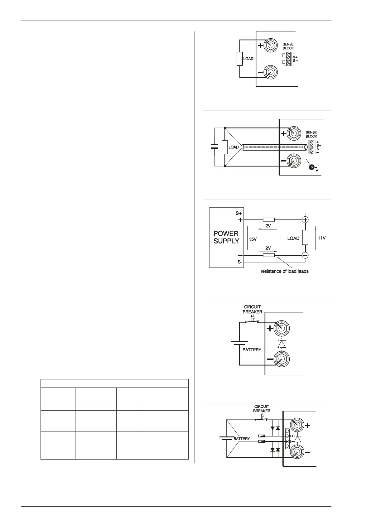
RE MOTE SENSING
• Not avail able on SM3004-D.
• Remove the links on the SENSE BLOCK (on rear panel) and
connect sense leads (thin shielded mea suring wires) to S+
and S–. See fig. 4 - 5 and fig. 4 - 6.
• With remote sensing the voltage on the load can be kept con -
stant. The voltage drop in the load leads will be com pensated.
This feature is not rec ommended for normal use, be cause it
can eas ily give prob lems.
• Max. 2 V per load lead can be compensated. Note that the
voltage drop in the leads de creases the max. output voltage
rating. In fig. 4 - 27 it can be seen that on a 15 V power supply
only 11 V will be available on the load when 2x 2 V com pensa-
tion is used.
• In or der to pre vent in terference it is ad visable to twist the
sense leads. To min imize the inductance in the load leads
keep the leads close to each other. The in ductance of the
loads leads could give a prob lem with pul sating loads. In this
case a large electrolytic ca pacitor in parallel with the load will
help. Check that the ca pacitor in combination with the load
leads does not form a resonant cir cuit re sulting in a large AC
current flowing in the leads.
• Since the volt me ter is in ternally con nected to the sens ing ter -
mi nals, it will au to mat i cally in di cate the voltage on the load.
Note that the voltage mea sured on the load will be lower than
on the out put terminals.
• The Over Volt age Pro tector mea sures the volt age on the out -
put terminals, so the OVP set ting should be in creased by the
total voltage drop in the load leads.
7)
BAT TERY CHARGER
• The CV / CC reg ulated power supplies are ideal battery charg-
ers. Once the output is set at the correct voltage the bat tery
will charge con stantly with out over charging. This can be use -
ful for emer gency power systems.
• Pro tec tive mea sures
Use a CIR CUIT BREAKER in se ries in or der to pro tect the
power sup ply from ac ci den tal re verse con nec tion, see fig.
4 - 8. The circuit breaker should have a DC voltage rat ing 2x
the bat tery voltage. Use the very fast type (Z), a type meant for
pro tect ing semi con duc tors.
The unit has a re verse di ode in par allel with the out put, this di -
ode and the wir ing can not with stand the thou sands of am-
peres sup plied by a wrongly connected battery.
Suggested Circuit Breakers for pro tection power supply
Model Type num ber
Cir cuit Breaker
Brand Re marks
SM1540-D S281 UC-Z 40 ABB
SM7020-D S281 UC-Z 20 ABB
ex tra par al lel
diode on out put
= Op tion P021
SM3004-D S282 UC-Z 4 ABB 2 poles in se ries,
ex tra par al lel
diode on out put
= Op tion P022
fig. 4 - 5
Lo cal sens ing
fig. 4 - 6
Remote sensing with shielded wires
fig. 4 - 7
Remote sensing, voltage drop in load leads sub -
tracts from max. output
fig. 4 - 8
Charging battery with a circuit breaker in se ries
fig. 4 - 9
Protecting sense wires with di odes

 Loading...
