SM1540-D SM7020-D SM3004-D DELTA ELEKTRONIKA BV
1989 rev. May 2008 OPERATING MAINTENANCE TROUBLE SHOOTING CALIBRATING Page 4 - 3
•
Re mote sens ing can not be rec ommended, be cause it easily
causes de fects in side the power sup ply in case of wrong con -
nec tion.
If you re ally need re mote sensing, please use the cir cuit in fig.
4 - 9. The in ternal cir cuit can be protected by rel atively small
anti-parallel di odes. To pro tect the anti-parallel di odes, please
connect the fuses in series as in dicated in fig. 4 - 9 . A practi-
cal choice for the fuses is 250 mA, the di odes can be any nor -
mal 3 or 5 A type.
• Note: The SM7020-D and SM3004-D need an ex tra par allel
diode on the out put, without this di ode the in ternal di ode will
still blow. The di ode should have a surge cur rent rating of
resp. 2000 and 3000 amps dur ing 1msec (I
FSM
= 2000 / 3000
A ). For the SM7020-D 2x BYT52PI200 and for the SM3004-D
2x BYT261PIV400 from ST will work. The SM7020-D with Op -
tion P021 and the SM3004-D with Op tion P022 have an ex tra
di ode built-in.
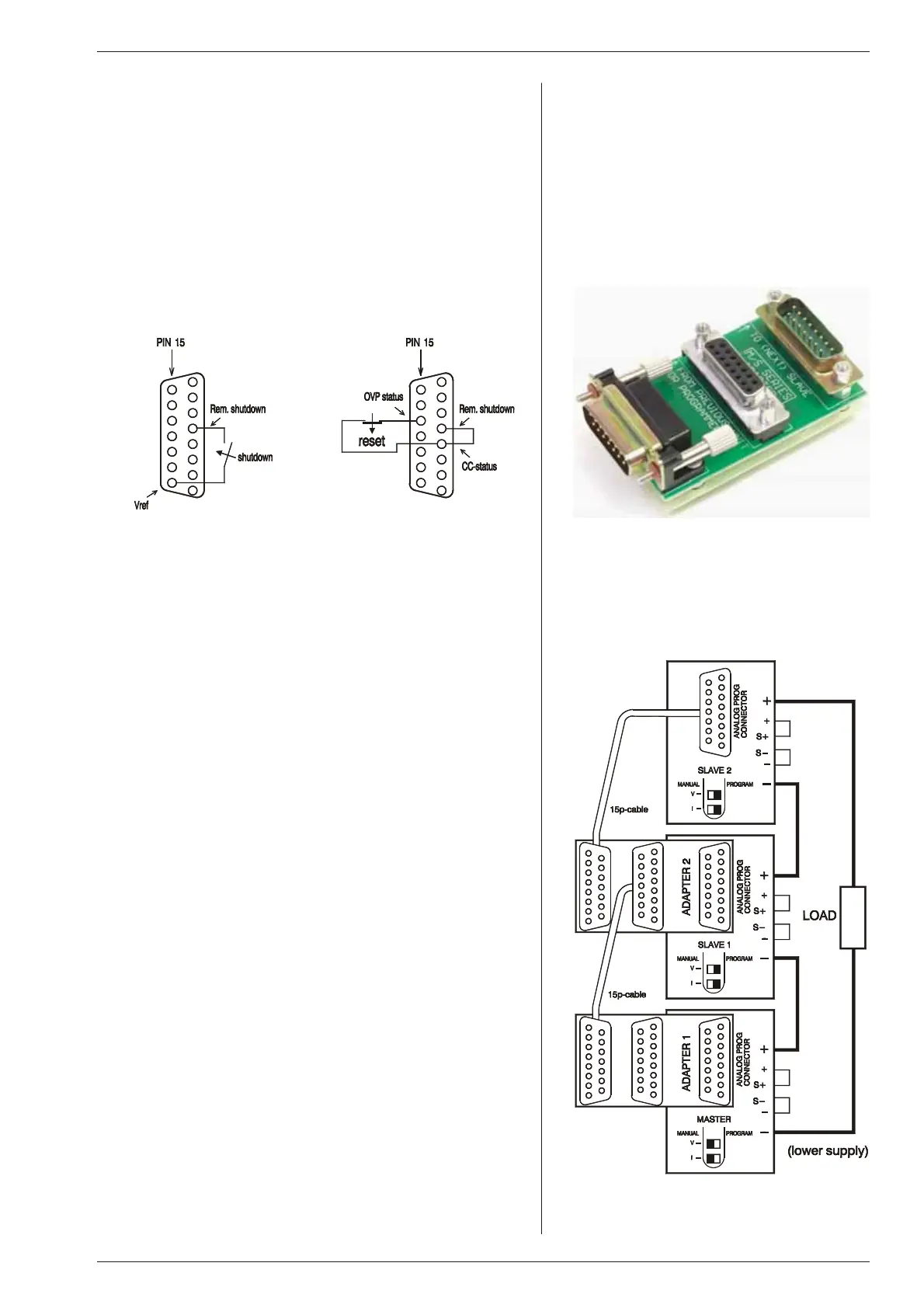
fig. 4 - 10
Left: remote ShutDown with switch,
Right: Over Current Trip
8) REMOTE SHUT DOWN / OVER CUR RENT TRIP
• The re mote ShutDown can be op erated with +5 V or a re lay
con tact, fig. 4 - 10.
• Using the remote ShutDown in put, an Over Cur rent Trip could
be made., fig. 4 - 10.
9)
MASTER / SLAVE SERIES OP ERATION
• For se ries op er a tion the MASTER / SLAVE SE RIES
ADAPTER
(δ-prod uct) must be used, see fig. 4 - 11.
The ad vantage is that the masters po sition can be the up per or
the lower unit (in par ticular for higher voltages; 150 V and
300 V). Other ad vantages are the fast and easy way of
connecting.
• First, connect output terminals and test sys tem in nor mal se-
ries op eration. Ensure that all (out put) power con nections are
reliable. An in terruption of one of the power leads can cause a
fuse to blow in the unit, see ''trou ble shoot ing''.
• The voltage drop in the con necting leads be tween the units
should be kept < 10 mV.
• Second, switch off all units. Con nect units as shown in fig.
4 - 12. Use standard 15 pole (1:1) shielded ca bles.
• The max. num ber of slaves is only limited by the max. total
voltage of 600 V.
• The AUTORANGING fea ture still works
10)
MASTER / SLAVE PAR AL LEL OP ER A TION
• Note: Master / Slave parallel is not recommended for more
than 4 units, con sult factory for us ing more than 4 power
sup plies in par al lel.
• First con nect output terminals and test sys tem in nor mal par al-
lel op eration. Ensure that all power con nections are reliable. An
interruption of one of the (output) power leads can cause a fuse
to blow in the unit, see “trou ble shoot ing”.
• Second, switch off all units. Plug in prog. connectors with the
con nec tions ac cord ing to fig. 4 - 13 (buss bar to pology). Always
use a shielded ca ble. The shielding must be connected to the
case of the supply.
Disconnect the links be tween the S– and – of the slaves only.
fig. 4 - 11
The Master / Slave Series Adapter,
supplied by Delta Elektronika
fig. 4 - 12
Master / Slave se ries con nection with
two M/S SE RIES ADAPTERS

 Loading...
