SM1540-D SM7020-D SM3004-D DELTA ELEKTRONIKA BV
1989 rev. May 2008 OPERATING MAINTENANCE TROUBLE SHOOTING CALIBRATING Page 4 - 1
OPERATING MANUAL
1) OPERATING THE UNIT FOR THE FIRST TIME
• Set the in put volt age se lec tor switch found on the rear panel to
the re quired in put voltage (110/230 V). A wrong setting can se ri-
ously dam age the unit. Do not switch the se lector switch when
the unit is in use.
• Check in put fuses. For 110 V op eration fuses have to be re-
placed. See text at rear panel.
• Check that there is no condensation on the unit. If there is, al low
some time to dry.
• Set the prog. switches on the rear panel on MAN UAL.
• Check that there is a link be tween + and S+ and be tween – and
S– on the SENSE BLOCK (on rear panel).
SM3004-D has no re mote sensing!
• Set OVP po tentiometer (on front panel) to max imum (fully clock-
wise), Use a screwdriver to set the OVP volt age.
• With high out put current (SM1540-D!) make sure to use low re -
sistive con nections be tween the power sup ply and the load:
- Mount the ca ble lugs be tween the two nuts and washers .
- Only use nuts and wash ers sup plied with the unit (tinned brass).
- Never use ex tra wash ers, spring wash ers , serrated locks etc.
• Switch on unit.
• Turn both the CV and CC po tentiometer a few turns clockwise. A
voltage should now be pres ent on the output.
• By pressing the DISPLAY CV/CC SETTING button the meters
will show the setting of the CV and CC po tentiometer.
• By press ing the DIS PLAY OVP SETTING button the volt me ter
will show the setting of the OVP po ten ti om e ter.
• When the power sup ply is used on a fixed out put voltage it is
highly rec ommended to set the Over Volt age Pro tector. As set
out in the following ta ble:
SM1540-D SM7020-D
range 0 - 35V
SM7020-D
range 35 - 70V
SM3004-D
range 0 - 150V
SM3004-D
range 150 - 300V
Vout + 2V Vout + 3V Vout + 5V Vout + 10V Vout + 25V
Ex am ple: For a SM7020-D set at 24 V out put voltage it is recom-
mended to set the OVP on 24 + 3 = 27 V.
• Check that the cool ing of the unit is not ob structed.
2)
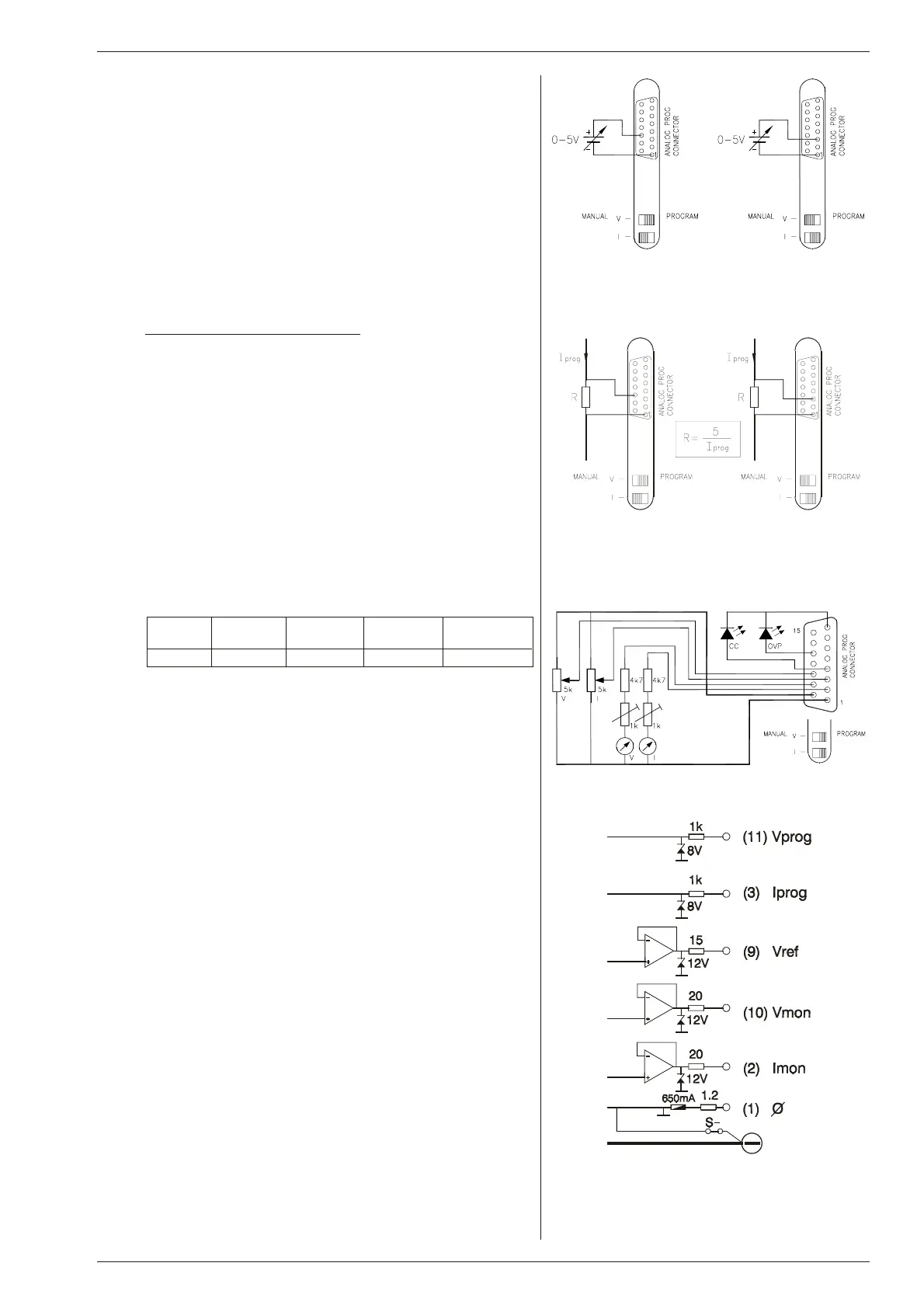
AN A LOG PRO GRAMMING
• Put the ap propriate switch(es) in the po sition PROGRAM.
• Connect the pro gramming voltage source(s) (0 - 5 V) to the AN A-
LOG PROG. CON NECTOR on the rear panel (see fig. 4 - 1 and
fig. 4 - 2). Al ways use a shielded ca ble for pro gramming.
• If only the voltage is pro grammed, the max imum current can still
be set with the CC po tentiometer and vice versa. If this is not de -
sirable the CC or CV can be set with an ex ternal po tentiometer, in
order to have a fixed set ting.
• CAU TION: The an alog in puts are not iso lated from the output.
The Ø of the prog. in put (pin 1) is in ternally con nected to the S–,
the S– is connected to the neg ative output. To pro tect the in ternal
wiring a 650 mA self-resetting fuse is con nected in se ries (F600
on P385, P386 or P387), see fig. 4 - 4.
For iso lated an a log pro gram ming the ISO AMP MOD ULE
(δ-prod uct) is rec ommended to avoid earth loops.
• To avoid hum or noise, the pro gramming ca ble may have to be
twisted in some cases.
• To pro gram the unit by current in stead of volt age, sim ply use a
parallel re sistor as a current to volt age con verter.
3)
IEEE488 / RS232 PRO GRAMMING
• With the ex ternal IEEE488 /RS232 in ter face PSC-488 mod ule /
PSC-232 mod ule (both
δ-prod ucts) sim ply con nect the prog.
connector of the power sup ply with the mat ing con nector of the
PSC-488 / PSC-232 (pin com patible). Always use a shielded ca -
ble.
• Set both prog. switches to the po sition pro gram.
• Both CV and CC can be pro grammed and read back. The CC and
OVP sta tus can also be read by the computer.
fig. 4 - 1
Pro gram ming by volt age
left voltage -, right current pro gramming
fig. 4 - 2
Pro gram ming by cur rent
left voltage -, right current pro gramming
fig. 4 - 3
Re mote con trol
fig. 4 - 4
In ter nal cir cuit of pro gram ming in puts and out puts
 Loading...


