SM1540-D SM7020-D SM3004-D DELTA ELEKTRONIKA BV
1989 rev. May 2008 DESCRIPTIONS Page 3 - 5
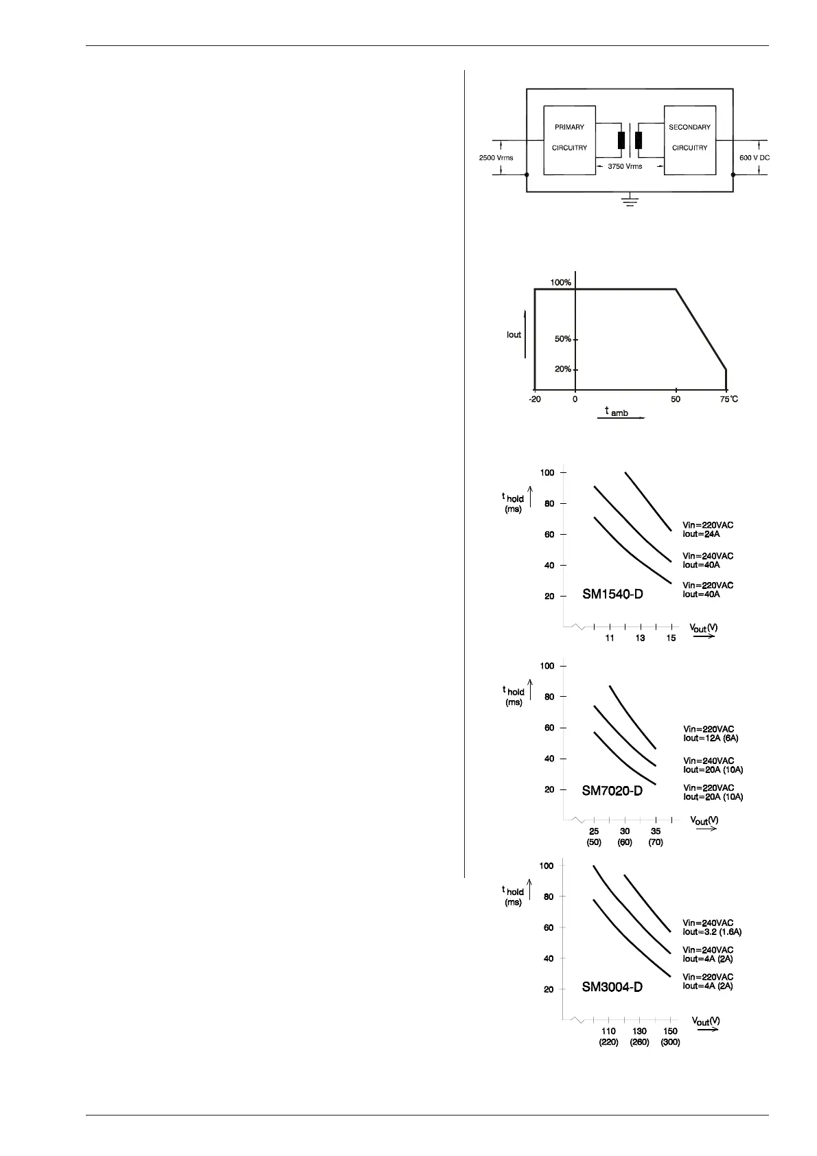
18) IN SU LA TION
For safety the in su la tion of the sep a rat ing com po nents (trans-
formers) be tween in put and out put is tested at 3750 Vrms dur ing
1 min ute. This is tested be fore as sembling.
Warn ing! The 3750 Vrms can not be tested af terwards on the
as sem bled unit be cause the in su la tion be tween the com po -
nents on the in put side to the case (like the bridge rec tifier) is
spec i fied at 2500 Vrms. Since the in sulation out put - case is low
(only 600 V DC) the in sulation of the pri mary components to
case will break down when 3750 Vrms is ap plied be tween in put
and out put (2500 Vrms + 600 V DC < 3750 Vrms). See also
fig. 3 - 19.
Note: when testing the in sulation, take care to charge and dis -
charge the capacitors be tween in put - case and out put - case
slowly (e.g. in one sec ond). This to prevent high peak currents,
which could de stroy the power sup ply. Make sure to have dis -
charged the capacitors completely be fore us ing it again.
19)
RFI SUP PRES SION
Both the in put and out put have RFI fil ters, re sulting in very low
conducted RFI to the line and load. Due to the out put fil ter the
output voltage is very clean, hav ing al most no spikes.
20)
OP ER ATING TEMP
At full power the op erating tem perature range is –20 to +50 °C.
From 50 to 75 °C the output cur rent has to be de rated lin early to
20 % at 75 °C. See fig. 3 - 20. These tem peratures hold for nor -
mal use, i.e. the air must be able to pass freely vertically along
and through the unit.
21)
THER MAL PRO TEC TION
A ther mal switch shuts down the out put in case of in sufficient
cooling. After cool ing down the unit will start work ing again. In
this con di tion the OVP led on the front panel will burn, and the
OVP sta tus output will be high.
22)
HOLD - UP TIME
The hold - up time de pends on the load, out put voltage and line
input voltage. A lighter load, a lower out put voltage or a higher
line in put voltage all re sult in a lon ger hold - up time, see fig.
3 - 21. For ex ample: the SM1540-D at 220 VAC in put and 12 V /
40 A out put will have a hold-up time of 50 ms.
23)
TURN ON DE LAY
The out put voltage is avail able 0.5 sec after mains switch on.
24)
IN RUSH CUR RENT
The in rush current is limited by a 50 Ohm PTC re sis tor, re sult ing
in a very low current dur ing switch on. The in put cur rent dur ing
switch on will be lower than dur ing op eration at full load.
fig. 3 - 19
In su la tion test voltages
fig. 3 - 20
Op er at ing tem per a ture ranges
fig. 3 - 21
Holdup time vs V
out with line in put
and I
out as pa ram e ter
 Loading...


