Delta-Q IC650 Charger Manual
2
www.delta-q.com
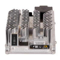
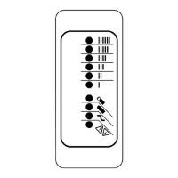
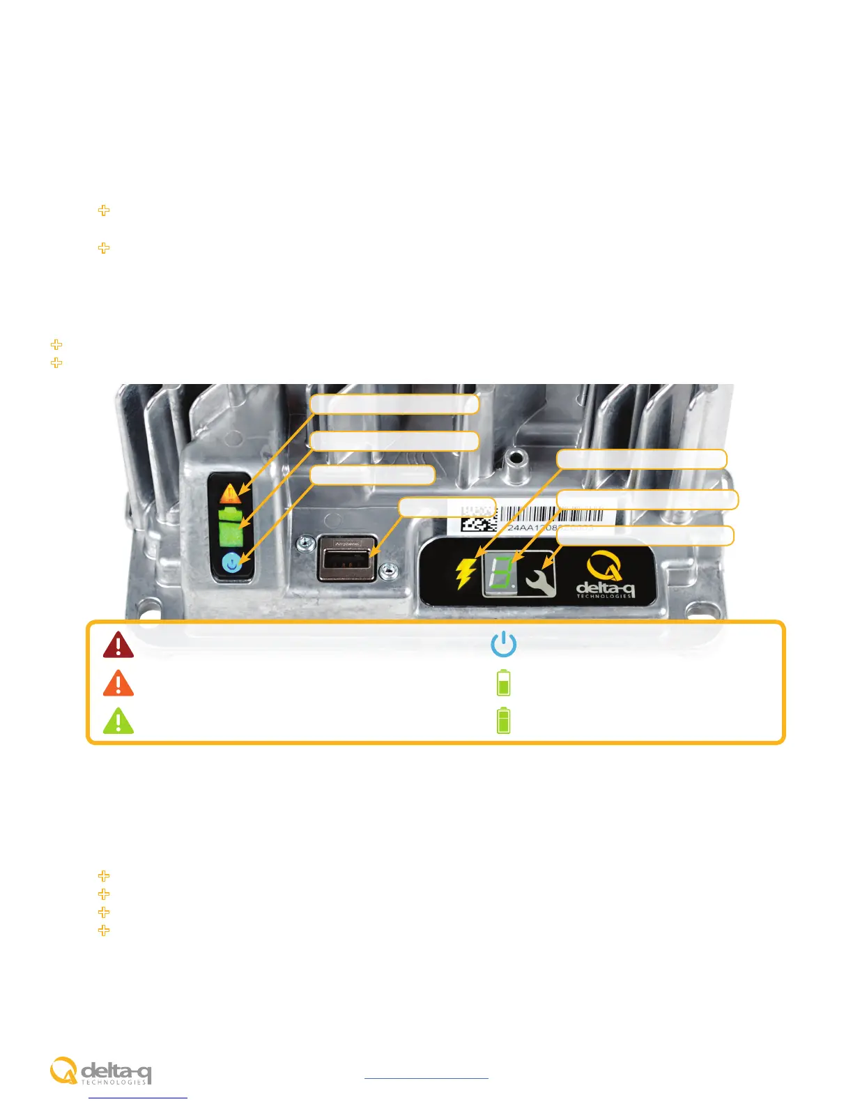
1. The USB Host Port allows data to be transferred to and from the charger using a standard USB flash drive, including the
downloading of charge tracking data and updating of the charger’s software and / or charge profiles.
2. The Charging Output Indicator means that the charger output is active, and there is a potential risk of electric shock.
3. The Charge Profile / Error Display shows one of four possible codes to indicate different conditions:
‘F’ codes meaning that an internal fault condition has caused charging to stop.
‘E’ codes meaning that an external error condition has caused charging to stop.
‘P’ code meaning that the charger programming mode is active.
‘USB’ code meaning that the USB interface is active, and the USB flash drive should not be removed.
The ‘E,’ ‘F’ and ‘P’ codes will appear, then are followed by three numbers and a period to indicate different conditions (e.g.
E-0-0-4). See the “Charger Fault Codes” or “Charger Error Codes” sections for details on these conditions and their solutions.
4. The Select Charge Profile Button is used to select a charge profile from those stored on the charger. Up to 25 charge
profiles can be stored. See the “Selecting A Charge Profile” section for instructions.
Operating Instructions
The charger may become hot during charging. Use hand protection to safely handle the charger during charging.
Extension cords must be 3-wire cord no longer than 30m (100’) at 10 AWG or 7.5m (25’) at 16 AWG, per UL guidelines.
Maintenance Instructions
1. Do not expose charger to oil, dirt, mud or direct heavy water spray when cleaning the vehicle or machine.
2. The enclosure of the charger meets IP66, making it dust-tight and protected against powerful water jets. The AC inlet
connection itself, when mated, is rated to IP20, which is not protected against water. Protect the AC connection if
used in wet or dusty environments.
3. If the detachable input power supply cord set is damaged, replace with a cord that is appropriate for your region:
North America: UL or CSA listed / approved detachable cord at least 1.8m in length (≥ 6 feet), 3 conductor,
16AWG minimum and rated SJT; terminated in a grounding type IEC 60320 C14 plug rated 250V, 13A minimum.
All other regions: Safety approved detachable cord, 3 conductor, 1.5mm² minimum, rated appropriately for
industrial use. The cord set must be terminated on one end with a grounding type input connector appropriate
for use in the country of destination and, on the other end, an output grounding type IEC 60320 C14 plug.
Fault / Error / USB Indicator
Battery Charging Indicator
AC Power Indicator
USB Host Port
1
Charging Output Indicator
2
Charge Prole / Error Display
3
Select Charge Prole Button
4
Solid red = Charger fault
See display panel for details
Flashing amber = External error condition - caution
See display panel for details
Flashing green = USB port active
Solid green = Safe to remove USB flash drive
Flashing green = Low state of charge
Solid green = High state of charge
Flashing green = High state of charge
Solid green = charge completed
Solid blue = AC power available
 Loading...