14
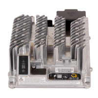
6.2 Signals and Control
Connector type: TE Connectivity AmpSeal 776262
Mating connector: TE Connectivity AmpSeal 776273-x series
This is a heavy-duty, automotive-grade, waterproof signal
connection system. When assembling, care must be taken
to ensure all unused signals (i.e. those without a wire)
are properly blocked with the appropriate part. When
assembled properly, it will provide a long service life.
Note: Pin numbers 1, 5, 6, 9, 10, and 14 are labeled on the
connector. These numbers are upside-down when the
connector is viewed from the back of the charger.
Pin
No.
Recommended
Wire Size
(AWG / mm
2
)
Description Detail
1 16-20 / 1.3-
0.52
CAN-GND Reference ground for CAN signals
2 Interlock 1 (NC) Interlock relay: Normally closed contact
3 Interlock 2 (COM) Interlock relay: Common contact. Recommend inline 0.5A fast-
blow fuse
4 Interlock 3 (NO) Interlock relay: Normally open contact
5 Battery Temp.
Sense ‘+’
Connect to NTC 10k 5% thermistor
6 CAN High See Communications section
7 Battery Negative Reference ground for battery signals
8 Enable / Disable Use for single-wire BMS control. See Communications section.
9 LIN bus See Communications section.
10 CAN Low See Communications section.
11 Comm Port Service use only.
12 LED Positive (+) For remote LED anode
13 LED Negative (-) For remote LED cathode
14 Battery Temp.
Sense Ground
Reference ground for battery temperature sensor signal
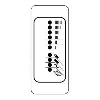
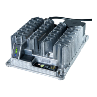
Figure 14. Signals and control connector
10
6
1
 Loading...