www. specselectonline.com
Page 2 of 6
203586
Rev.A
ELECTRONIC FLUSH VALVE INSTALLATION INSTRUCTION
STEP 1 – ROUGH-IN FLUSH VALVE,
FRAME OR BOX
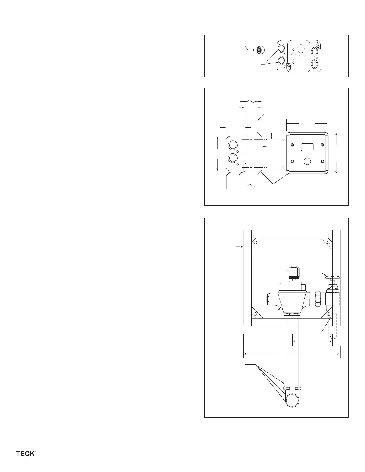
• Install and attach flush valve to water supply as per Fig. 1C.
4” Sensor Plate Models
If Hardwire Operated
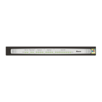
• 102mm (4”) box is supplied, remove suitable knockouts and insert cable
bushing as per Fig. 1A.
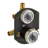
• Rough-in box for sensor location as per Fig. 1D. Note: Solenoid extension
cord supplied with the trim is 1220mm (48”) long.
• Securely attach box to wall structure.
• Run suitable wire from 24vac power source into box. Use wire which
complies with local electrical codes for 1 amp load. No. 18 cable is usually
sufficient.
• Attach supplied plasterguard as per Fig. 1B to ensure sensor mounting holes
are positioned correctly.
4” Sensor Plate Models
If Battery Operated
• 102mm (4”) box and 4” box extension is supplied. Remove suitable knockout
as per Fig 1A.
• Attach box extension to front of the box.
• Rough-in box assembly for sensor location as per Fig. 1D Note: Solenoid
extension cord supplied with the trim is 1220mm (48”) long.
• Securely attach box to wall structure.
• Attach supplied plasterguard as per Fig. 1B to ensure sensor mounting holes
are positioned correctly.
14” and 14” X 20” Sensor Plate Models
• 12” or 12” X 18” frame is supplied. Rough in frame so the valve will be
positioned as shown per Fig. 1D.
• Securely attach frame to wall structure.
(1/4”) Min.
(1 3/5”) Max.
1” I.P. Inlet
Nut, etc.
Fixture Specified.
Elbow, etc.
 Loading...