213777, Rev. A
www. s p e c s e l e c t . c o m
Page 5
ELECTRONIC FLUSH VALVE INSTALLATION INSTRUCTIONS
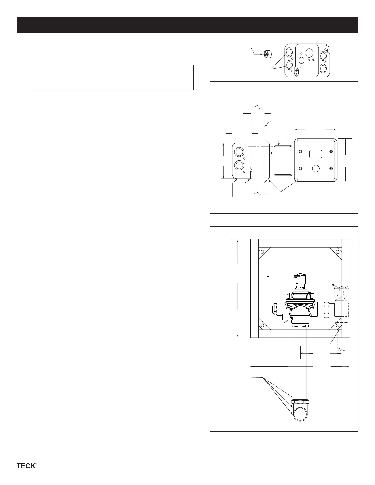
STEP 1 - ROUGH-IN FLUSH VALVE, FRAME
OR BOX
NOTE: Due to excess back pressure of low ow water
closets, outlet tubes must be braced to prevent tubes
from disconnecting.
• Install and attach ush valve to water supply as per Fig.1C.
4” Sensor Plate Models
If Hardwire Operated
• 102 mm (4”) box is supplied, remove suitable knockouts and insert
cable bushing as per Fig. 1A.
• Rough-in box for sensor location as per Fig. 1D.
Note: Solenoid extension cord supplied with the trim is 1,220 mm (48”)
long.
• Securely attach box to wall structure.
• Install CSA and/or UL approved Class 2 transformer or equivalent
in a convenient location or in a pipe chase. (Do NOT install the
transformer inside the control box.)
• Run suitable wire from 24VAC power source into box. Use wire which
complies with local electrical codes for 1 amp load. No.18 cable is
usually sucient.
• Attach supplied plasterguard as per Fig. 1B to ensure sensor mounting
holes are positioned correctly.
4” Sensor Plate Models
If Battery Operated
• 102 mm (4”) box and 4” box extension is supplied. Remove suitable
knockout as per Fig. 1A.
• Attach box extension to front of the box.
• Rough-in box assembly for sensor location as per Fig. 1D.
Note: Solenoid extension cord supplied with the trim is 1,220 mm (48”)
long.
• Securely attach box to wall structure.
• Attach supplied plasterguard as per Fig. 1B to ensure sensor mounting
holes are positioned correctly.
14” and 14” X 20” Sensor Plate Models
• 12” or 12” x 18” frame is supplied. Rough in frame so the valve will be
positioned as shown per Fig. 1D.
• Securely attach frame to wall structure.
Cable Bushing
Knockouts
Fig. 1A
6mm
(1/4”) Min.
35mm
(1-3/4”) Max.
Finished Wall
Vandal Proof
Screws (4)
Stainless Steel Coverplate
55mm
(2-5/32”)
102mm
(4”)
Plaster
Guard
114mm
(4-1/2”)
Sensor
Standard Electrical Box
102 x 102mm (4” x 4”)
Small Sensor Box
Fig. 1B
Wheel
Handle
Stop
Flushvalve
121mm
(4-3/4”)
305mm
(12”) Square
1” I.P. Inlet
Outlet Parts
Tubing, Elbow,
Wall and Spud
Flange, Spud
Nut, etc.
Supplied as
required for
Fixture specified.
Except for:
3/4” and 1-1/4” Top
Inlet Urinal Fixtures
where exposed
Tubing, Flanges,
Elbow, etc.
(Supplied by Others)
Fig. 1C
114mm
(4-1/2”)
305mm (12”)
Square
Access
Box Frame
 Loading...