6
ASSEMBLY
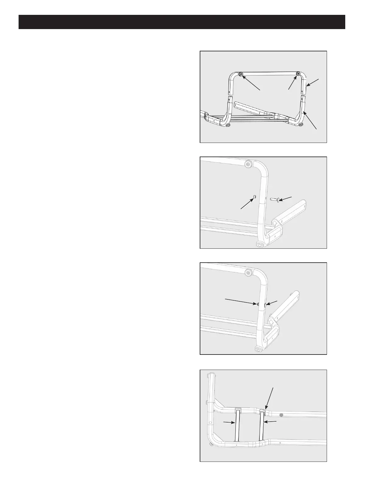
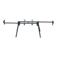
VERTICAL SUPPORT LEG ASSEMBLY
Attach the Right Leg Support Rod (Right Leg Support Rod
not shown in Figure 1) and Left Leg Support Rod (D) to the
Support Rod Connect Tube (G). (Figure 1)
Note: Rubber Feet will point outward away from support rods
G and D.
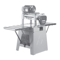
Secure Assembly with M8 x 35mm Carriage Bolt (R) and
M8 Locknut (S) ensuring that square on Carriage Bolt (R) is
properly tted into square hole on the outer side of the tube.
(Figure 2)
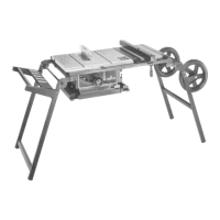
Tighten M8 Locknut (S) with Wrench (J) provided. Repeat on
other side of this assembly step. (Figure 3)
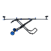
Place Straight Cross Connect Tube (I) and Angled Cross
Connect Tube (H) inside leg Support Assembly as shown.
(Figure 4)
Figure 4
Figure 1
Figure 2
Figure 3
G
D
S
R
S
J
I
H
1
Rubber Feet