8
ASSEMBLY
ASSEMBLE SUPPORT LEG ROD ASSEMBLY TO PEDAL ASSEMBLY
ASSEMBLE UPPER END OF SUPPORT
LEG ROD ASSEMBLY TO MAIN
FRAME ASSEMBLY
ATTACH HANDLE TO STAND
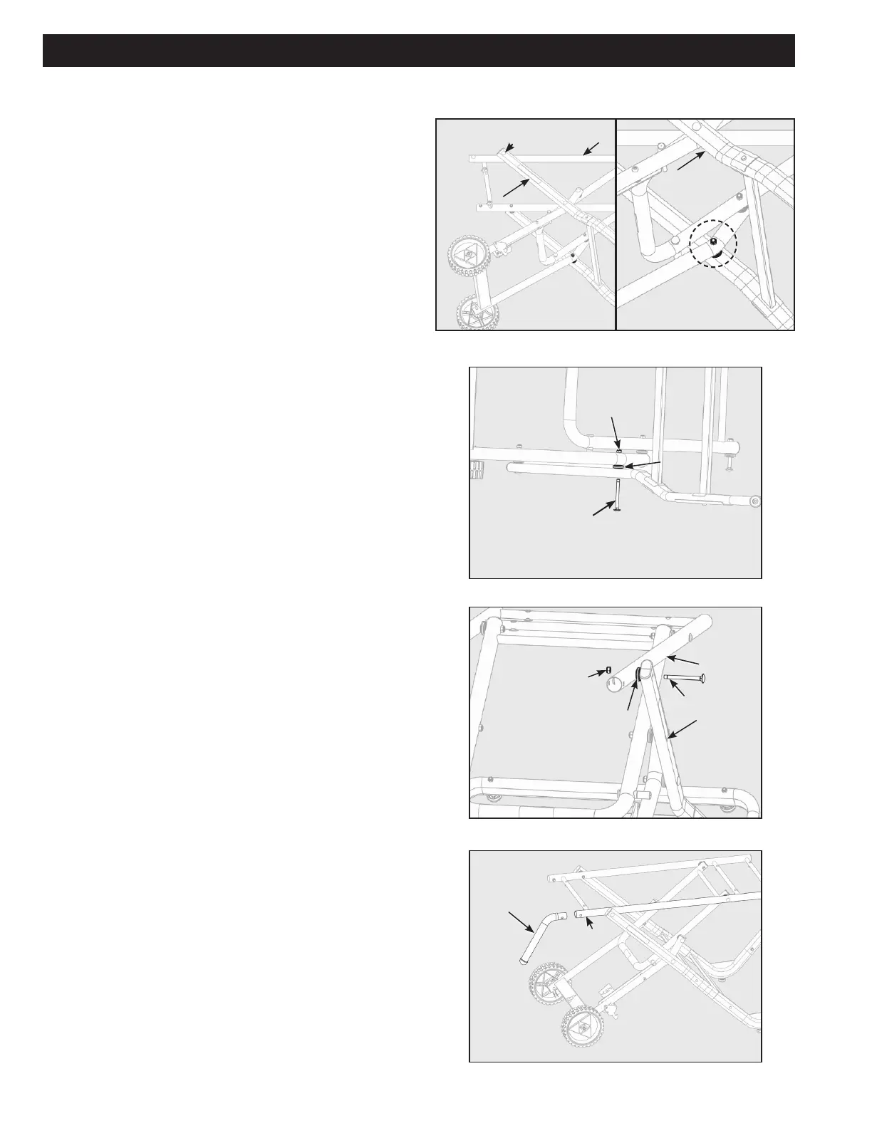
Note: Lay unit on side for the following assembly steps.
Attach Support Leg Rod Assembly (1) to the Pedal Assembly
(A) so that the "L" portion of the Support Rod Assembly goes
out and away from the Pedal Assembly as shown in Figure 9a.
Attach assembly with 2 of the M8 x 78mm Carriage Bolts (L),
Plastic Spacer (M) and M8 Locknut (N) (one on each side).
Ensure Carriage Bolt (L) ts properly into square hole in tube.
Plastic Spacer (M) will be between the tubes as shown in
Figure 10. Tighten Locknut (N) with included Wrench to secure
assembly so that Plastic Spacer (M) is a snug t between the
two tubes. Repeat these steps on other side of this assembly.
Note: Do not over tighten Locknut (N). Over tightening will
aect stand folding performance.
When installed correctly, square hole in upper end of Support
Rod Assembly (1) should be able to line up with the second
square hole from handle side of the Main Frame Assembly (B)
as shown in Figure 10.
Attach upper end of Support Rod Assembly (1) to the Main
Frame Assembly (B) using 2 of the remaining M8 x 78mm
Carriage Bolts (L), Plastic Spacer (M) and M8 Locknut (N).
Ensure Carriage Bolt (L) ts properly into square hole in
tube. Plastic Spacer (M) will be between the tubes as shown
in Figure 11. Tighten Locknut (N) with included Wrench (J)
to secure assembly so that Plastic Spacer (M) is a snug t
between the two tubes. Repeat on other side of this assembly.
Note: Do not overtighten Locknut (N). Over tightening will
aect stand folding performance.
Insert Handle (F2) into Main Frame Assembly (B) as shown in
Figure 12. Align 1st hole in Main Frame Assembly (B) with the
hole in the handle.
Figure 12
Figure 11
Figure 10
Figure 9a Figure 9b
1
B
1
L
B
M
N
F2
B
Hole Alignment
M
L
N
1