EasyManua.ls Logo

Delta AS02HC-A User Manual

Delta AS02HC-A
632 pages
To Next Page IconTo Next Page
To Previous Page IconTo Previous Page
Page #443 background imageLoading...
Page #443 background image
Chapter 11 DeviceNet Master Scanner Module AS01DNET-A
11-17
1
1
Position of
AS01DNET
on the right
of the PLC
Output mapping area (for sending data to
the slave)
Input mapping area (for receiving data from
the slave)
D register Mapping area
Data
size
D register Mapping area
Data
size
output data
area
words data area words
Note: See Section 11.4.5 for further explanation of scan-list node status indication areas and module status indication
areas. The input and output mentioned here are defined in the perspective of the master of the entire fieldbus system.
When AS01DNET works in slave mode, the input and output mapping areas for AS01DNET at different positions
of the right of AS PLC are listed in the following table.
Position of
AS01DNET on
the right of the
PLC
Area for sending data to the master Area for receiving data from the master
D register Data length D register Data length
1
D26100~D26199 100 words D26000~D26099 100 words
2
D26500 D26599
100 words
D26400 D26499
100 words
3
D26900 D26999
100 words
D26800 D26899
100 words
4
D27300 D27399
100 words
D27200 D27299
100 words
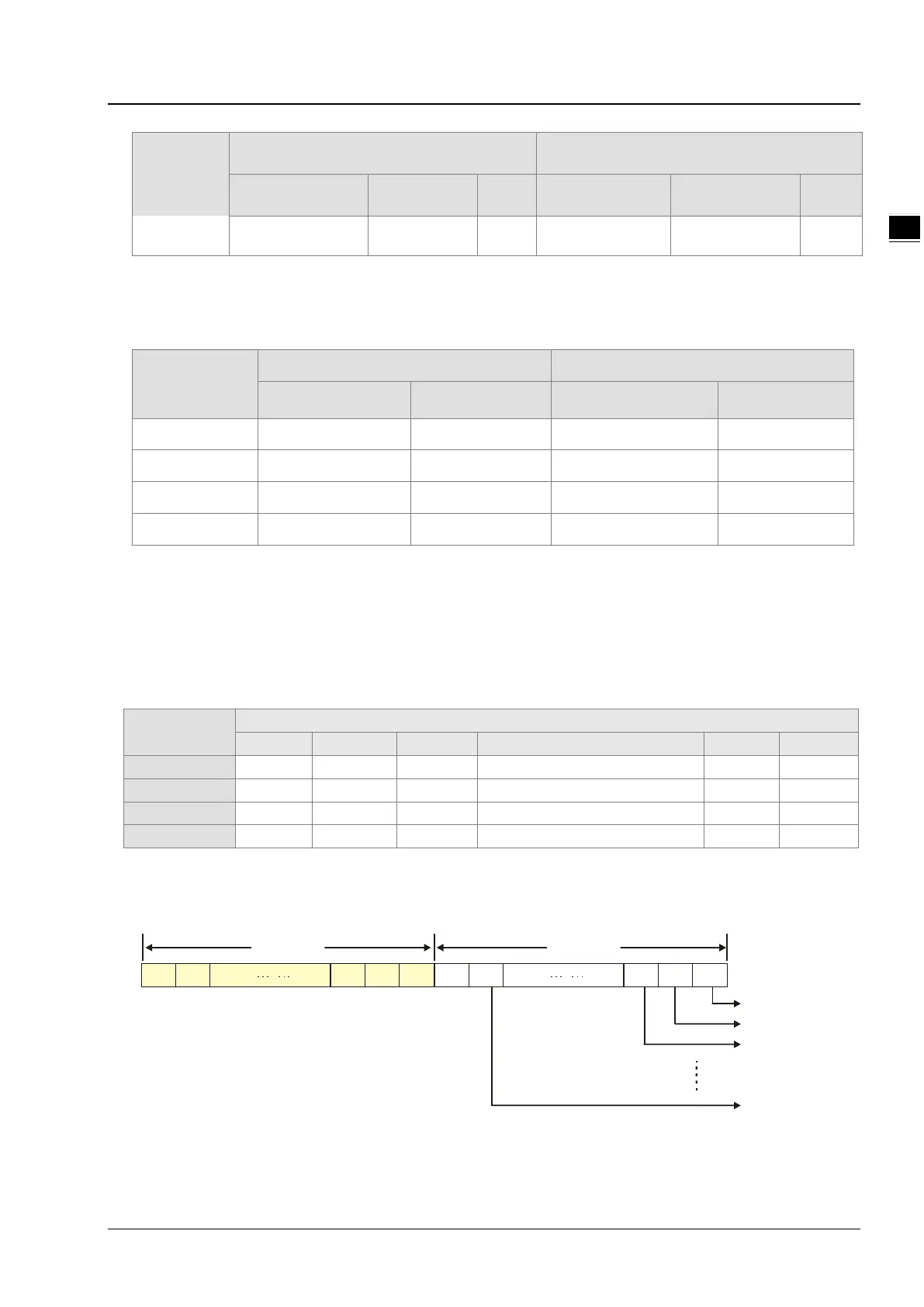
11.4.4 Bit-strobe Command
11.4.4.1. Bit-strobe Work Principle
Bit strobe is one of the standard DeviceNet I/O transmission methods. The command length is fixed to 8 bytes, i.e. 64
bits. (Maximum 64 stations exist in a DeviceNet network.) One bit corresponds to one node. The following table takes
the first AS01DNET on the right of AS PLC for example.
Bit-strobe
register
Corresponding network node
b15
b14
b13
… …
b1
b0
D26100
Node 15
Node 14
Node 13
… …
Node 1
Node 0
D26101
Node 31
Node 30
Node 29
… …
Node 17
Node 16
D26102
Node 47 Node 46 Node 45 … … Node 33 Node 32
D26103
Node 63 Node 62 Node 61 … … Node 49 Node 48
When the value of bit0 of D26100 is 0, node 0 is selected and need return data to the master.
When the values of bit0 and bit1 of D26100 are both 0, node 0 and node 1 are selected and they need return data to the
master.
b0b1b17 b15 b14b30 b2b18 b16b31
D6283
Node 0
Node 1
Node 2
Node 14
D6282
In the bit-strobe method, the master does not send control data to the slave node. However, the slave node need return
I/O data to the master if the corresponding bit is set to 0. If the corresponding bit is set to 1, the slave node does not need
to return I/O data to the master.

Table of Contents

Question and Answer IconNeed help?

Do you have a question about the Delta AS02HC-A and is the answer not in the manual?

Delta AS02HC-A Specifications

General IconGeneral
BrandDelta
ModelAS02HC-A
CategoryNetwork Hardware
LanguageEnglish

Summary

Chapter 1 Introduction

1.3 Installation

Provides step-by-step instructions for installing modules, terminal blocks, and extension cards.

Chapter 2 Digital Input/Output Modules

2.1 Digital Input/Output Module Specifications

Details the electrical and functional specifications for digital input/output modules.

Chapter 3 Analog Input Module AS04/08AD

3.2 Specifications and Functions

Covers detailed electrical and functional specifications for analog input modules.

3.2.7 Wiring

Provides detailed precautions and external wiring diagrams for analog input modules.

3.3 HWCONFIG in ISPSoft

Guides on using HWCONFIG software for module configuration, including initial setup, version check, and online mode.

3.4 DIADesigner+ (Hardware Configuration)

Guides on using DIADesigner+ for hardware configuration, including initial setup, module addition, and parameter settings.

3.5 Troubleshooting

Provides information on error codes and troubleshooting procedures for common issues.

Chapter 4 Analog Output Module AS04DA

4.2 Specifications and Functions

Covers detailed electrical and functional specifications for the AS04DA analog output module.

4.2.6 Wiring

Provides detailed precautions and external wiring diagrams for the AS04DA analog output module.

4.3 HWCONFIG in ISPSoft

Guides on using HWCONFIG software for module configuration, including initial setup, version check, and online mode.

4.4 DIADesigner+ (Hardware Configuration)

Guides on using DIADesigner+ for hardware configuration, including initial setup, module addition, and parameter settings.

4.5 Troubleshooting

Provides information on error codes and troubleshooting procedures for common issues.

Chapter 5 Analog Input/Output Module AS06XA

5.2 Specifications and Functions

Covers detailed electrical and functional specifications for the AS06XA analog input/output module.

5.2.6 Wiring

Provides detailed precautions and external wiring diagrams for the AS06XA analog input/output module.

5.3 HWCONFIG in ISPSoft

Guides on using HWCONFIG software for module configuration, including initial setup, version check, and online mode.

5.4 DIADesigner+ (Hardware Configuration)

Guides on using DIADesigner+ for hardware configuration, including initial setup, module addition, and parameter settings.

5.5 Troubleshooting

Provides information on error codes and troubleshooting procedures for common issues.

Chapter 6 Temperature Measurement Module AS04/06RTD

6.2 Specifications and Functions

Covers detailed electrical and functional specifications for temperature measurement modules.

6.2.8 Wiring

Provides detailed precautions and external wiring diagrams for temperature measurement modules.

6.3 HWCONFIG in ISPSoft

Guides on using HWCONFIG software for module configuration, including initial setup, version check, and online mode.

6.4 DIADesigner+ (Hardware Configuration)

Guides on using DIADesigner+ for hardware configuration, including initial setup, module addition, and parameter settings.

6.5 Troubleshooting

Provides information on error codes and troubleshooting procedures for common issues.

Chapter 7 Temperature Measurement Module AS04/08TC

7.2 Specifications and Functions

Covers detailed electrical and functional specifications for temperature measurement modules.

7.2.8 Wiring

Provides detailed precautions and external wiring diagrams for temperature measurement modules.

7.3 HWCONFIG in ISPSoft

Guides on using HWCONFIG software for module configuration, including initial setup, version check, and online mode.

7.4 DIADesigner+ (Hardware Configuration)

Guides on using DIADesigner+ for hardware configuration, including initial setup, module addition, and parameter settings.

7.5 Troubleshooting

Provides information on error codes and troubleshooting procedures for common issues.

Chapter 8 Load Cell Module AS02LC

8.2 Specifications

Covers detailed electrical specifications for the AS02LC load cell module.

8.2.6 Wiring

Provides external wiring diagrams for four-wire and six-wire load cell connections.

8.3 Making Adjustments

Guides on making adjustments to the load cell module, including steps for adjusting points and using the LC Wizard.

8.5 Troubleshooting

Provides information on error codes and troubleshooting procedures for common issues.

Chapter 9 Serial Communication Module AS00SCM

9.7 Error Codes

Lists error codes for AS00SCM-A when acting as a communication module or remote module.

Chapter 10 Function Cards

Chapter 11 DeviceNet Master Scanner Module AS01DNET-A

Chapter 12 Positioning Module AS02/04

12.4 Troubleshooting

Provides information on error codes and troubleshooting procedures for common issues.

Chapter 13 IO-Link Communication Module AS04SIL

Chapter 14 High Speed Counter Module AS02HC

14.5 Troubleshooting

Provides information on error codes and troubleshooting procedures for common issues.

Related product manuals