EasyManua.ls Logo

Delta AS02HC-A User Manual

Delta AS02HC-A
632 pages
To Next Page IconTo Next Page
To Previous Page IconTo Previous Page
Page #458 background imageLoading...
Page #458 background image
AS Series Module Manual
11-32
11
S3 is DeviceNet service code:
Service code
Explanation
0x01
Get all attributes (Get_Attribute_All)
0x02
Set all attributes (Set_Attribute_All)
0x0E
Get one single attribute (Get_Attribute_Single)
0x10
Set one single attribute (Set_Attribute_Single)
S4, S5 and S6 represent Class ID, Instance ID and Attribute ID respectively.
S7 is the written-data size with the unit: Byte.
S8 is the start device where written data are stored. The data are arranged in the order from low byte to high
byte.
S9 is the communication timeout time within the range: 1~100 and with the unit: 0.1 second.
S10 is the times of re-transmission within the range: 0~3. When communication timeout occurs, the
communication will be resent
D3 represents the error codes to read and write.
Error Code
Explanation
Code 1 (High Byte)
Code 2 (Low Byte)
XX FF Not conform to the DeviceNet standard
20
01
The target slave does not exist.
20 02 Unable to make the connection with the slave
20
03
Sending explicit message failed.
16
00
Explicit message response timeout.
D4 is the read-data size with the unit: Byte.
D5 is the start device where read data are stored. The data are arranged in the order from low byte to high
byte.
D1 and D2 are communication completion flag and error flag respectively.
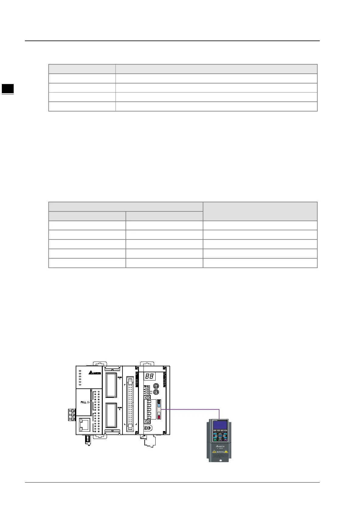
Application Example 1
Control requirement: when M0=ON, read the data of class1>>instance1>>attribute1 of the DeviceNet function
card CMC-DN01.
Connection Figure
01DNET
MS
NS
x10
x10
IN 0
IN 1
Node Address
RTU Master Slave/
40
5
6
7
3
2
1
4
OUT
0
10
11
9
8
Ethernet
2
3
IN
4
6
5
7
1
0
10
11
9
8
COM1
AS324MT
COM2
BAT. L OW
POWER
RUN
ERROR
2 1
DeviceNet

Table of Contents

Question and Answer IconNeed help?

Do you have a question about the Delta AS02HC-A and is the answer not in the manual?

Delta AS02HC-A Specifications

General IconGeneral
BrandDelta
ModelAS02HC-A
CategoryNetwork Hardware
LanguageEnglish

Summary

Chapter 1 Introduction

1.3 Installation

Provides step-by-step instructions for installing modules, terminal blocks, and extension cards.

Chapter 2 Digital Input/Output Modules

2.1 Digital Input/Output Module Specifications

Details the electrical and functional specifications for digital input/output modules.

Chapter 3 Analog Input Module AS04/08AD

3.2 Specifications and Functions

Covers detailed electrical and functional specifications for analog input modules.

3.2.7 Wiring

Provides detailed precautions and external wiring diagrams for analog input modules.

3.3 HWCONFIG in ISPSoft

Guides on using HWCONFIG software for module configuration, including initial setup, version check, and online mode.

3.4 DIADesigner+ (Hardware Configuration)

Guides on using DIADesigner+ for hardware configuration, including initial setup, module addition, and parameter settings.

3.5 Troubleshooting

Provides information on error codes and troubleshooting procedures for common issues.

Chapter 4 Analog Output Module AS04DA

4.2 Specifications and Functions

Covers detailed electrical and functional specifications for the AS04DA analog output module.

4.2.6 Wiring

Provides detailed precautions and external wiring diagrams for the AS04DA analog output module.

4.3 HWCONFIG in ISPSoft

Guides on using HWCONFIG software for module configuration, including initial setup, version check, and online mode.

4.4 DIADesigner+ (Hardware Configuration)

Guides on using DIADesigner+ for hardware configuration, including initial setup, module addition, and parameter settings.

4.5 Troubleshooting

Provides information on error codes and troubleshooting procedures for common issues.

Chapter 5 Analog Input/Output Module AS06XA

5.2 Specifications and Functions

Covers detailed electrical and functional specifications for the AS06XA analog input/output module.

5.2.6 Wiring

Provides detailed precautions and external wiring diagrams for the AS06XA analog input/output module.

5.3 HWCONFIG in ISPSoft

Guides on using HWCONFIG software for module configuration, including initial setup, version check, and online mode.

5.4 DIADesigner+ (Hardware Configuration)

Guides on using DIADesigner+ for hardware configuration, including initial setup, module addition, and parameter settings.

5.5 Troubleshooting

Provides information on error codes and troubleshooting procedures for common issues.

Chapter 6 Temperature Measurement Module AS04/06RTD

6.2 Specifications and Functions

Covers detailed electrical and functional specifications for temperature measurement modules.

6.2.8 Wiring

Provides detailed precautions and external wiring diagrams for temperature measurement modules.

6.3 HWCONFIG in ISPSoft

Guides on using HWCONFIG software for module configuration, including initial setup, version check, and online mode.

6.4 DIADesigner+ (Hardware Configuration)

Guides on using DIADesigner+ for hardware configuration, including initial setup, module addition, and parameter settings.

6.5 Troubleshooting

Provides information on error codes and troubleshooting procedures for common issues.

Chapter 7 Temperature Measurement Module AS04/08TC

7.2 Specifications and Functions

Covers detailed electrical and functional specifications for temperature measurement modules.

7.2.8 Wiring

Provides detailed precautions and external wiring diagrams for temperature measurement modules.

7.3 HWCONFIG in ISPSoft

Guides on using HWCONFIG software for module configuration, including initial setup, version check, and online mode.

7.4 DIADesigner+ (Hardware Configuration)

Guides on using DIADesigner+ for hardware configuration, including initial setup, module addition, and parameter settings.

7.5 Troubleshooting

Provides information on error codes and troubleshooting procedures for common issues.

Chapter 8 Load Cell Module AS02LC

8.2 Specifications

Covers detailed electrical specifications for the AS02LC load cell module.

8.2.6 Wiring

Provides external wiring diagrams for four-wire and six-wire load cell connections.

8.3 Making Adjustments

Guides on making adjustments to the load cell module, including steps for adjusting points and using the LC Wizard.

8.5 Troubleshooting

Provides information on error codes and troubleshooting procedures for common issues.

Chapter 9 Serial Communication Module AS00SCM

9.7 Error Codes

Lists error codes for AS00SCM-A when acting as a communication module or remote module.

Chapter 10 Function Cards

Chapter 11 DeviceNet Master Scanner Module AS01DNET-A

Chapter 12 Positioning Module AS02/04

12.4 Troubleshooting

Provides information on error codes and troubleshooting procedures for common issues.

Chapter 13 IO-Link Communication Module AS04SIL

Chapter 14 High Speed Counter Module AS02HC

14.5 Troubleshooting

Provides information on error codes and troubleshooting procedures for common issues.

Related product manuals