AS Series Module Manual
2- 8
AS64AN02T-A
8
9
92
75
8
2
Y0
40
3
7
6
5
4
13
11
12
10
8
9
Y3
14
15
2
64AN
40
Y1
0
1
2
1
0
Y2
PWR
OUT
1
0
10
88
98.3
1
4
5
2
3
6
7
38.2
35
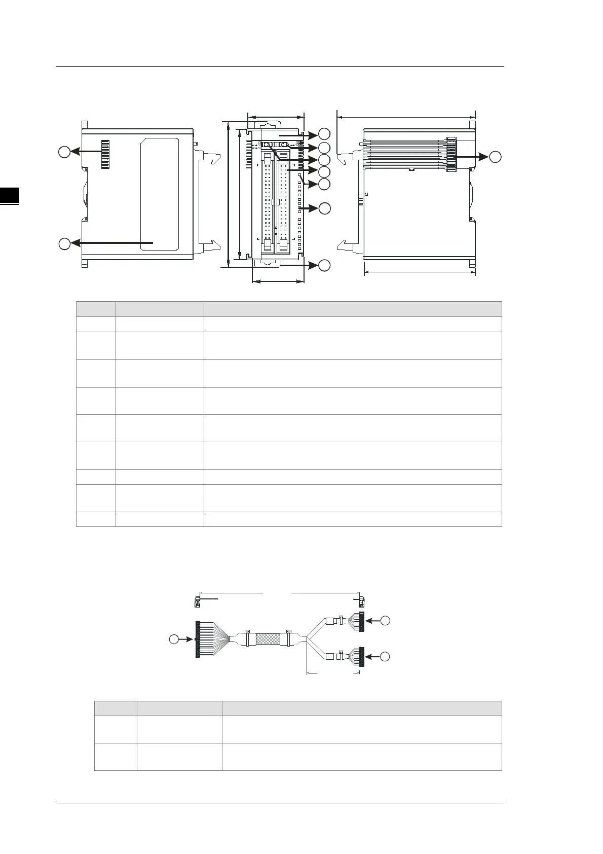
Unit: mm
1 Model name Model name of the module
2
LED indicator
Switches the LED indicators to their represented outputs.
3
LED indicator
switch 2
Switches the LED indicators to their represented outputs.
4 ML connector
For the external I/O connecting cables UC-ET010-24D, UC-ET020-
5
Power LED
Indicates the power status of the module
6
Output LED
If there is an output signal, the output LED indicator is ON.
8
External module
Connects the modules
ML connector, extension cable, and wiring modules
1. Extension Cable UC-ET010-24D (1M) / UC-ET020-24D (2M) / UC-ET030-24D (3M)
Length
3 9 40
1 2
500 +10m m
-
39 40
21 2 2
19 2 0
1 2
#1
#2
1
2
2
Unit: mm
1 IDC 40-pin terminal
Connects a digital input/output module and an external terminal
2 IDC 20-pin terminal
Connects the external terminal modules UB-10-ID16A/UB-10-