AS Series Module Manual
11-18
11.4.5 Network Node Status Display
11.4.5.1. Scan-List Node Status Indication
The following table takes the first AS01DNET on the right of AS PLC for example. AS01DNET master can monitor whether
the configured slave is online or not in real time and have the status of the configured slave mapped to one bit. Users can
get the status of network nodes by monitoring the contents in D26000~D26003. The corresponding relationships between
devices in the PLC and network nodes are shown in the following table. If the node in Scan List is normal, the corresponding
bit is OFF. If the node in Scan List is abnormal, the corresponding bit is ON.
Register in
the PLC
Corresponding network node
11.4.5.2. Module Status Indication
The following table takes the first AS01DNET on the right of AS PLC for example. Users can get the status of the network
node by monitoring the content in D26004. When the module works normally, the content in D26004 is 0. When the module
is initializing, the content in the high byte of D26004 is 1 and the content in the low byte is 0. When an error occurs in the
module, the content in the high byte of D26004 is 2 and the content in the low byte is an error code. For details on error
codes, see Digital Displayer.
Register in
the PLC
D26004
Module status
(0:Normal,1:Initializing,2:error)
Error code in the module
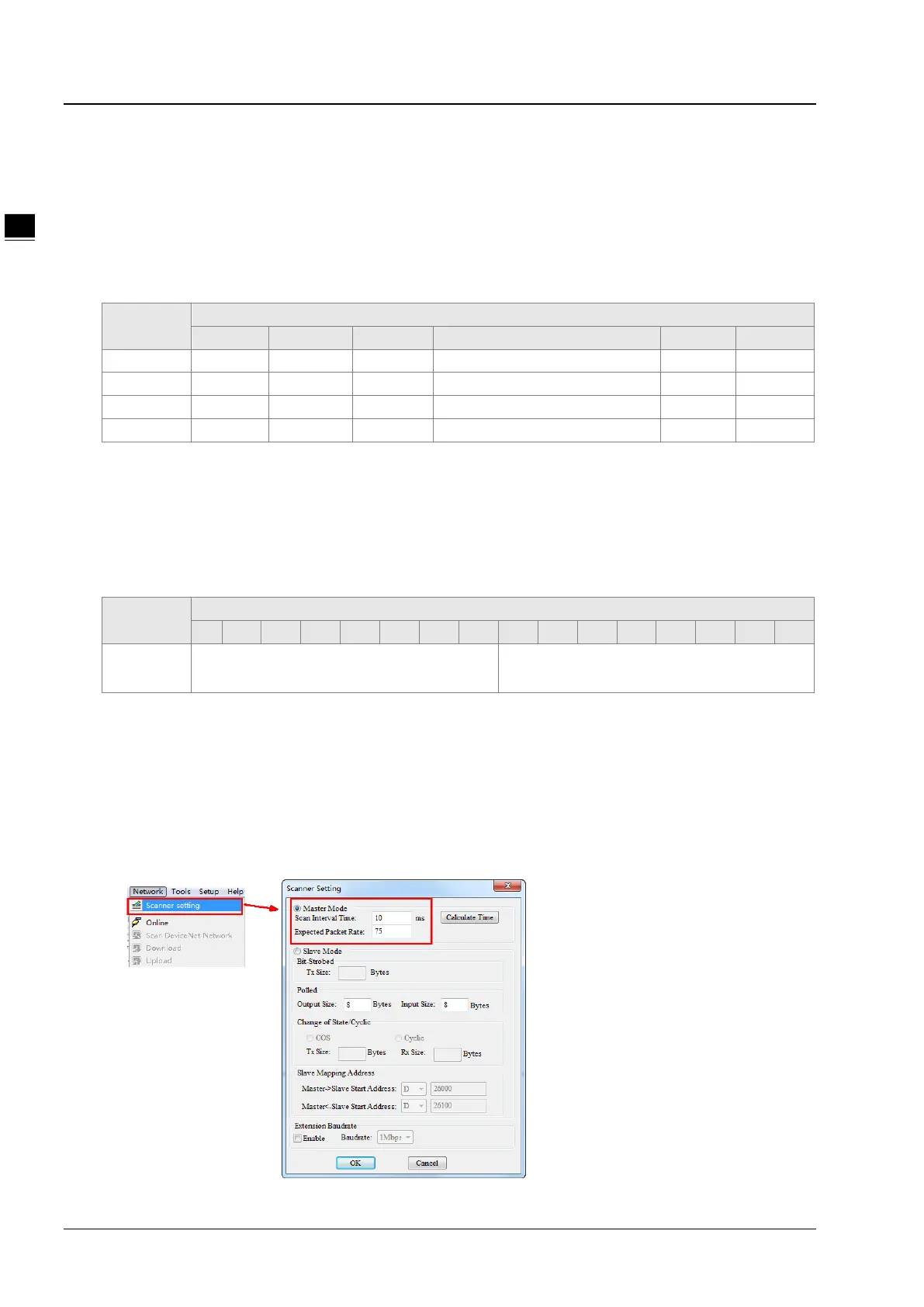
11.4.6 Setting the Time for Data Exchange between Master and
Slaves
When AS01DNET works in master mode, the period of time for a data exchange between master and all slaves need be
set. Master and all salves will periodically perform the data exchange based on the set time. See the following explanation
for details. Click menu Network >> Scanner Setting on the DeviceNet Builder software page. The Scanner Setting
window appears as below.
 Loading...