Do you have a question about the Delta AX-308EA0MA1T and is the answer not in the manual?
Introduces AX-3 Series CPU functions, devices, module tables, troubleshooting, and more.
Lists related manuals for AX-3 Series programmable logic controllers for further information.
Details the classification, model names, and descriptions of various modules for the AX-3 Series.
Provides an overview of DIADesigner-AX, a programming tool for Delta PLCs, focusing on its features.
Highlights the key features and capabilities of the DIADesigner-AX software for automation projects.
Details general specifications including operating temperature, humidity, vibration, and safety standards.
Covers functional and electrical specifications for AX-3 Series CPU modules.
Details the functional specifications for AX-308EA0MA1T and AX-364ELA0MA1T CPU modules.
Provides electrical specifications for CPU modules, including supply voltage and power consumption.
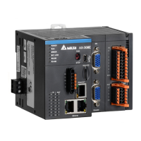
Illustrates the physical profiles and dimensions of AX-308EA0MA1T and AX-364ELA0MA1T CPU modules.
Details the input and output terminal connections for AX-308EA0MA1T and AX-364ELA0MA1T CPU modules.
Covers the general specifications for AS-PS02 and AS-PS02A power supply modules.
Details general specifications for power supply modules, including voltage and current outputs.
Illustrates the physical profiles and dimensions of the AS-PS02 power supply module.
Details the terminal connections for AS-PS02 and AS-PS02A power supply modules.
Explains how AS Series modules can be connected to AX-3 Series CPUs.
Provides instructions for installing hardware components like memory cards and PLCs.
Guides on how to insert and remove memory cards from the CPU module slot.
Details the procedure for installing or replacing the button cell battery for the real-time clock.
Provides guidelines for installing the AX-3 Series PLC within a control cabinet, including environmental and anti-interference measures.
Covers the process of installing and uninstalling the DIADesigner-AX software.
Provides step-by-step instructions for installing the DIADesigner-AX software on a computer.
Explains the procedure for uninstalling the DIADesigner-AX software from the computer.
Guides on starting the DIADesigner-AX software and setting up communication with the PLC.
Provides initial steps for starting the DIADesigner-AX software after installation.
Details the process of setting up communication between DIADesigner-AX and the PLC.
Introduces DIADesigner-AX as an open platform for PLC development and industrial automation.
Guides on how to create a new project within the DIADesigner-AX software.
Explains how to configure various settings on the Device Page in DIADesigner-AX.
Details the configuration of CPU parameters, including communication settings.
Covers data types and variable declaration methods in DIADesigner-AX projects.
Lists and describes various data types available in DIADesigner-AX projects.
Explains rules for identifiers, multiple uses, and declaration of variables in DIADesigner-AX.
Discusses task configuration, including defining tasks, priorities, and types.
Details how to configure tasks, including rules for processing order and task types.
Describes the hardware configuration environment and tools within DIADesign-AX.
Explains how to add extension modules to the AX-3 Series PLC using DIADesign-AX.
Provides instructions on how to remove extension modules from the AX-3 Series PLC configuration.
Details the process of copying and pasting extension modules within the hardware configuration.
Explains how to cut and paste extension modules in the hardware configuration.
Introduces the Network Configuration tool for configuring networks in a project.
Provides an introduction to network configuration capabilities like creating networks and setting up EtherCAT.
Explains basic knowledge about devices, networks, and device names for network configuration.
Guides on creating network topologies by adding devices and establishing connections.
Introduces motion control programming elements like devices, symbols, and instructions.
Details the process of creating motion control projects, including flowcharts and steps.
Covers the procedure and examples for commissioning motion control axes.
Outlines the steps involved in building a motion control commissioning process.
Illustrates setting axis parameters before performing commissioning using software.
Introduces motion control devices used for configuring motion axes.
Provides an overview of motion control devices and their purpose in configuring motion axes.
Explains the role of axes in motion control, including servo drives, encoders, and virtual axes.
Details the steps for configuring a single axis, including EtherCAT settings.
Covers settings for axis groups, enabling linear and circular interpolation with multiple axes.
Lists and describes variables generated for single axes and axis groups in projects.
Guides on motion control programming, including program architecture and function blocks.
Explains various motion control functions like single-axis control and velocity control modes.
Provides practical programming examples for motion control functionalities.
Introduces the OPC UA server included with DIADesigner-AX for variable access via clients.
Guides on creating a new DIADesigner-AX project for OPC UA access.
Details how to set up a connection with the UaExpert OPC UA client.
Explains the process of creating certificates for secure OPC UA server and client connections.
Guides on creating a certificate for the DIADesigner-AX OPC UA Server using Matrikon FLEX OPC UA Editor.
Introduces the EtherCAT bus as an Ethernet-based fieldbus for industrial communication.
Highlights the features of the EtherCAT network, including communication rates and data structures.
Details the process of setting up the EtherCAT Master configuration in DIADesigner-AX.
Guides on setting up EtherCAT slaves, including scanning the network or adding from a product list.
Introduces Modbus serial communication, supporting RS-232 and RS-485 ports.
Details the Modbus serial port capabilities, including master and slave configurations.
Guides on setting up the Modbus Serial Master for communication with slaves.
Details how to set up the Modbus Serial Slave device for communication.
Introduces Ethernet communication, supporting Modbus TCP and EtherNet/IP.
Details setting up the Ethernet adapter device and configuring Ethernet parameters.
Guides on setting up the Modbus TCP Master (Client) for communication.
Details setting up the Modbus TCP Slave (Server) for communication.
Provides basic troubleshooting steps, error identification, and clearing error states.
Outlines fundamental steps for troubleshooting potential operational errors.
Explains methods to clear error states, including CPU resets and software operations.
Provides a flowchart for troubleshooting based on error occurrences and LED indicators.
Guides on viewing PLC logs for events, error codes, and system messages.
Details troubleshooting for CPU modules, focusing on error codes and LED indicators.
Addresses issues indicated by the ERROR LED blinking every 0.5 seconds on CPU modules.
Troubleshoots issues related to the ERROR LED blinking rapidly every 0.2 seconds.
Provides solutions for ERROR LED indicators that blink slowly every 3 seconds.
Explains troubleshooting when the BAT. LOW LED indicators are constantly ON.
Addresses issues indicated by the BAT. LOW LED blinking every 0.5 seconds.
Covers other troubleshooting scenarios not covered in previous sections.
Details troubleshooting for function blocks, specifically DL_BuiltInIO_AX3.
Provides troubleshooting for errors related to the DL_BuiltInIO_AX3 function block.
Addresses errors and warnings related to motion control instructions from DL_MotionControl.
Covers troubleshooting for I/O modules, including analog and temperature modules.
Details troubleshooting for analog and temperature I/O modules.
Provides troubleshooting steps for Loadcell Modules AS02LC.
Lists error codes and LED indicators for CPU modules and their descriptions.
Details error codes and their corresponding LED indicator status for CPU modules.
Lists error codes and LED indicators for Analog and Temperature modules.
| Power Supply | 300W |
|---|---|
| Wattage | 300 W |
| Model | AX-308EA0MA1T |
| Type | Power Supply |
| Output Type | DC |