2. Programming Concepts
D
Content
EX2
SS2
SA2
SE
SX2
Attrib.
Latch
-ed
Default
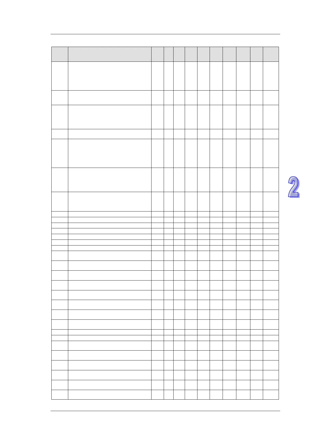
D1252
Set value for COM3 (RS-485) data
receiving time-out (Unit: 1ms, min. 50ms,
value smaller than 50ms will be regarded
as 50ms) (only applicable for MODRW/RS
instruction) In RS instruction, no time-out
setting if “0” is specified
ES2/
EX2
╳ ○ ╳
50 - - R/W NO 50
D1253
COM3 (RS-485) communication error code
(only applicable for MODRW/RS
ES2/
EX2
╳ ○
╳
0 - - R/W NO 0
D1254
Enter the number of output points on DIO
module for the PLC to check if the number
is matched with the value in D1143 when
power-on. Available for ES2/EX2/ES2C:
V3.62, ES2E: V1.48 or later
ES2/
EX2
╳ ╳ ╳
- - - R/W YES 0
D1255*
COM3 (RS-485) PLC communication
address
╳ ○
○
50 - - R/W YES 1
D1256
↓
D1295
For COM2 RS-485 MODRW instruction.
D1256~D1295 store the sent data of
MODRW instruction. When MODRW
instruction sends out data, the data will be
stored in D1256~D1295. Users can check
the sent data in these registers.
○ ○ ○ ○
0 - - R NO 0
D1296
↓
D1311
For COM2 RS-485 MODRW instruction.
D1296~D1311 store the converted hex
data from D1070 ~ D1085 (ASCII). PLC
automatically converts the received ASCII
data in D1070 ~ D1085 into hex data.
○ ○ ○ ○
0 - - R NO 0
D1312*
Specify the number of additional pulses for
additional pulses output and Z-phase
seeking function of ZRN instruction (Has to
○ ╳ ○ ○
0 0 - R/W NO 0
○
○
○
○
○
○
○
○
○
○
○
○
○
○
○
○
○
○
○
○
○
○
○
○
Year of RTC: 00 ~ 99 (A.D.)
○
○
○
○
D1320* ID of the 1
st
right side module
╳ ╳ ╳
0 - - R NO 0
D1321* ID of the 2
nd
right side module
╳ ╳ ╳
0 - - R NO 0
D1322* ID of the 3
rd
right side module
╳ ╳ ╳
0 - - R NO 0
D1323* ID of the 4
th
right side module
╳ ╳ ╳
0 - - R NO 0
D1324* ID of the 5
th
right side module
╳ ╳ ╳
0 - - R NO 0
D1325* ID of the 6
th
right side module
╳ ╳ ╳
0 - - R NO 0
D1326* ID of the 7
th
right side module
╳ ╳ ╳
0 - - R NO 0
D1327* ID of the 8
th
right side module
╳ ╳ ╳
0 - - R NO 0
PV of Y2 pulse output (Low word)
○
○
○
○
PV of Y2 pulse output (High word)
○
○
○
○
D1338 PV of Y3 pulse output (Low word)
○ ○ ○
- - - R/W NO 0
D1339 PV of Y3 pulse output (High word)
○ ○ ○
- - - R/W NO 0
D1340
Start/end frequency of the 1
st
group pulse
output CH0 (Y0, Y1)
○ ○ ○ ○
100 - - R/W NO 100
D1343
Ramp up/down time of the 1
st
group pulse
output CH0 (Y0, Y1)
○ ○ ○ ○
100 - - R/W NO 100
D1348*
When M1534 = ON, set the ramp-down time
of CH0 (Y0, Y1) pulse output in D1348.
○ ○ ○ ○
100 - - R/W NO 100
D1349*
When M1535 = ON, set the ramp-down time
of CH1 (Y2, Y3) pulse output in D1349.
○ ○ ○ ○
100 - - R/W NO 100