5. Sequential Function Chart
If M1014 is used, and M1040 is On, the steps in the same sequence will be cleared to Off.
Ladder diagram:
S24
S21
S
S0
S
S23
S
X2
S24
S
S25
S
S0
X7
RET
Using OUT S0
If M1040 is On, the state transfers to
S21 in the OUT sequence. If X2 is On,
the state of S21 will be cleared, ,and wil
not be transferred to S24.
If M1040 is On, the state transfers to
S25 in the OUT sequence. If X7 si On,
the state of S25 will be cleared, and
will not be transferred to S0.
Using OUT S24
Driving the jumping of step
Returning to the initial step
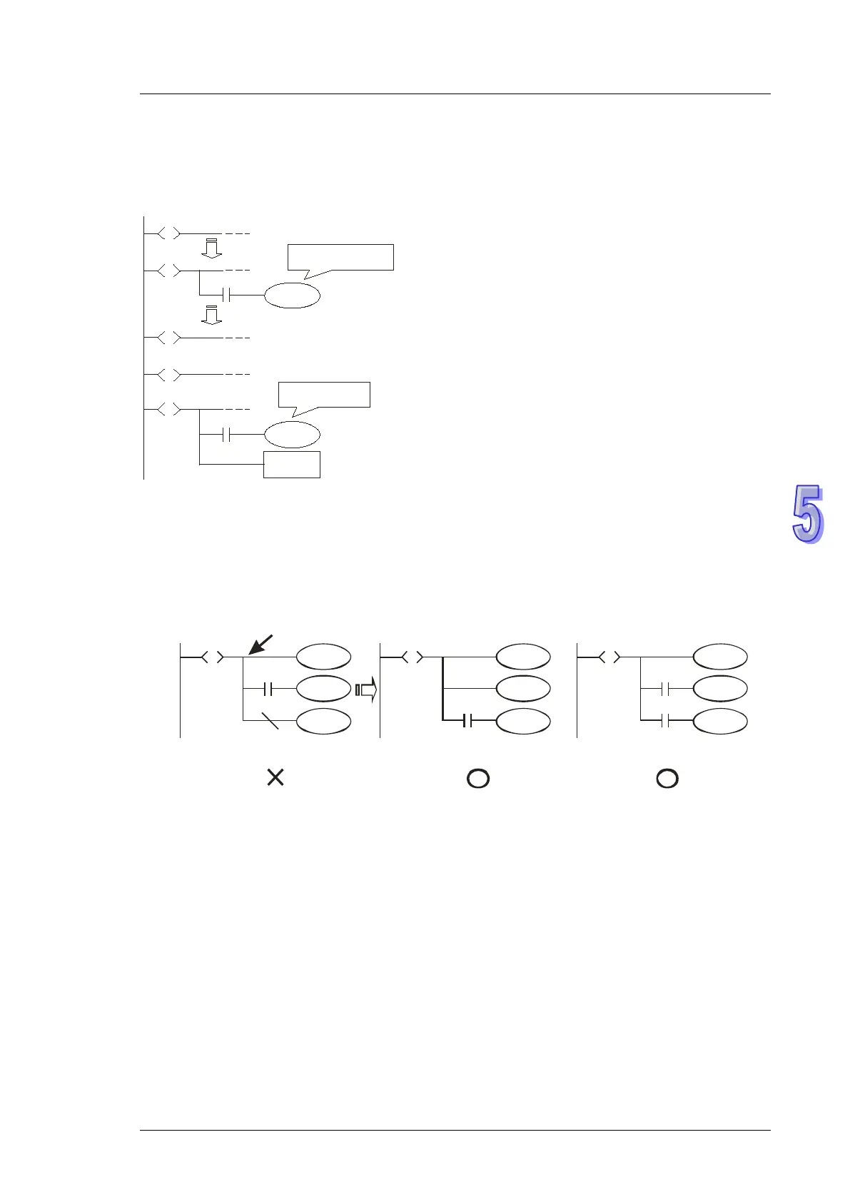
Cautions for Driving Output Point:
Once LD or LDI instructions are written into the second line after the step point, the bus will not be
able to connect output coils directly otherwise errors will occur when compiling the ladder diagram.
The following diagram explains the methods for correcting the ladder ion correct diagram.
Y0
S
S
Y1
Y2
M0
n
Y0
S
S
Y2
Y1
n
M0
Y0
S
S
Y1
Y2
M0
n
M1000
BUS
or
Modify the
position of M0.
Normally open
contact in RUN
mode
Restrictions on Using Certain Instructions:
Serial/parallel circuits or instructions in general ladder diagram are also applicable in step points of
STL diagram. However, there are restrictions on some of the instructions. Care should be taken
when using the instructions listed in the table below.