30
M4 screw
head
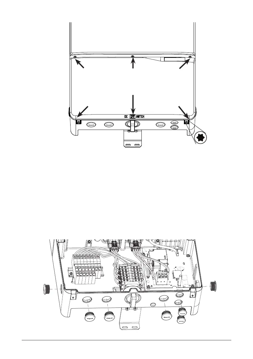
Figure 23: Removing the wiring box cover
1. Place DC Disconnect switch in “OFF” position. Please note the cover cannot be
removed when the DC Disconnect switch is in the “ON” position.
2. Remove the 5 cover screws indicated above with a T20 Torx screw driver
3. Lift the cover upward and place o to the side.
DC Switch in OFF position
4.8.3 Wiring box conduit plugs
Figure 24: Locations of wiring box conduit plugs
Conduit plugs are provided for 3/4 inch and ½ inch conduit ttings. If conduit tting used is bet-
ween 3/4 inch and ½ inch , an appropriate conduit reducer should be used.
1 in.
3/4 in.
1 in.
1 in.
 Loading...


