MODELS SMT130/SMT130H/SMT130M/SMT150/SMT150D
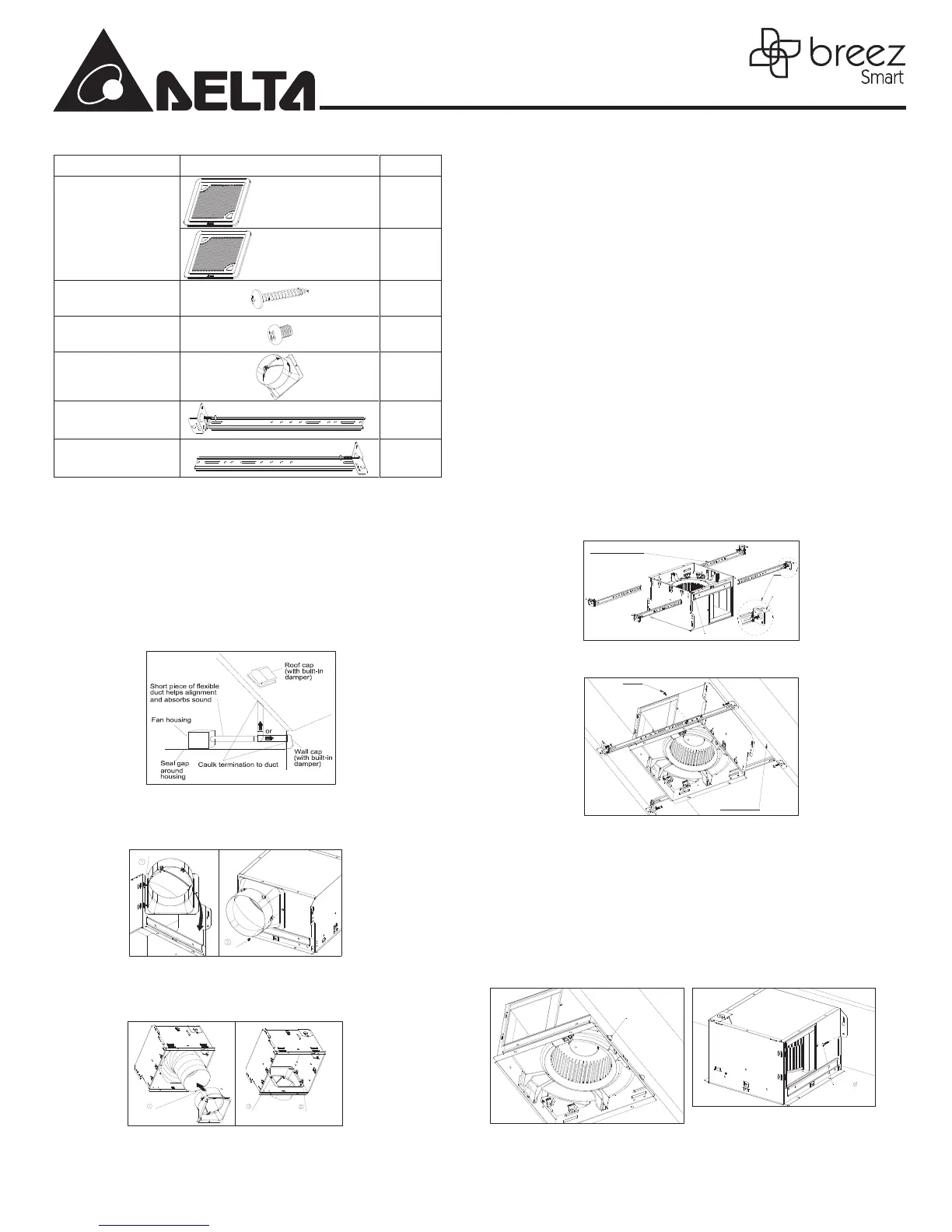
SUPPLIED ACCESSORIES
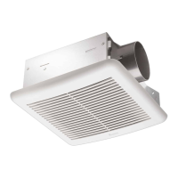
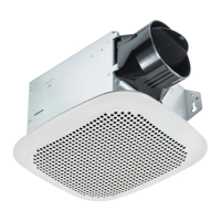
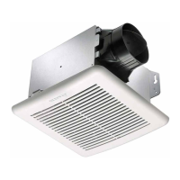
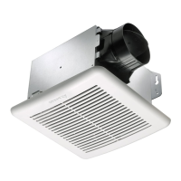
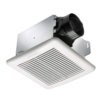
Grille
For models of:
SMT130, SMT130H,
SMT150, SMT150D
1
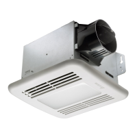
For model of:
SMT130M
1
Tapping Screw
(ψ4x25)
5
Screw
(#8-32x1/4”)
5
Duct connector
1
Suspension bracket I
13”(318.5mm)
2
Suspension bracket II
13”(318.5mm)
2
INSTALLATION
Proper insulation around the fan to minimize building heat
loss and gain. The ducting from this fan to the outside of
the building has a strong effect on the air flow, noise and
energy use of the fan. Use the shortest, straightest duct
routing possible for best performance, and avoid installing
the fan with smaller ducts than recommended. Insulation
around the ducts can reduce energy loss and inhibit mold
growth. Fans installed with existing ducts may not achieve
their rated air flow.
Attach duct connector
Option1, attach the duct connector from outside, and
secure by using one screw (#8-32x1/4” ).
Insert tab into hole in housing
Screw from Parts Bag
Option2, remove the motor assembly, attach the duct
connector from the housing can inside, and secure by
using one screw (#8-32x1/4” ). Insert and secure motor
assembly.
Pull existing ductwork
into Housing
Screw from
Parts Bag
Insert tab into hole in
housing
Note: Remove the tape from the damper and before installation.
Install the housing (I)-using suspension brackets
1. Sliding suspension brackets are available to allow for
positioning of the housing anywhere between joists
up to a span of 24”.
2. Insert the suspension brackets into the channels on
the housing. Make sure the tabs face up as shown.
(Fig. C ) Extend the suspension brackets to fit the
width of the joists. Hold the fan in place by wrapping
the suspension bracket tabs around the bottom o
f
the joist. Make sure the fan body is level and
perpendicular to the joist. (Fig. D )
3. Ensure that the distance between the ceiling and fan
body is appropriate for mounting the grille.
4. Secure the suspension brackets to the joists with
nails or by using the tapping screws (ψ4x25) through
holes near nails.
5. Secure the suspension bracket to the fan body using
the screws (#8-32 x 1/4").
6. Follow steps 2 to 6 of the installation instructions to
complete the installation work.
Channel
Suspension Bracket
Tab Face
Fig. C
Bottom of Joist
Joist
Joist
Fig. D
Install the housing (II)-using mounting tabs
Slotted tabs are provided to locate housing ush with 1/2”
ceiling material. Bend tabs outwards 90° (Use a screw
driver if desired) and position housing so that tabs rest
against bottom edge of the joists (or front of the stud). Nail
the housing to the joist or stud using four screws to ensure
a solid, quiet installation.
(Fig. E & F)
Joist
Tabs
Fig. E
Screw 4X25
Joist
Fig. F