- 7 -
VDC
+
PLC Rela
output
Smaller power
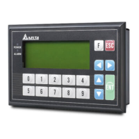
D: 1N4001 diode or equi valent com ponent
D
F i gur e11
R
Y
C0
ZDD
VDC
+
La rger power and
frequent on/of f
ZD: 9V Z ener, 5W
F igur e 12
PLC Rela
output
D: 1N4001 diode or equi valent com ponen t
R
Y
C0
R
C
PLC Rela
output
AC loa d
R: 100~ 120
C: 0.1~0.24uF
Figure 13
R
C1
Y
○
1
DC power supply
○
2
Emergency stop: An external switch is
used.
○
3
Fuse: To protect the output circuit, a fuse having a breaking capacity within the range
between 5 A and 10 A is connected to the common terminal.
○
4
Transient voltage suppressor: It increases the life span of the terminal.
1. Diode suppression of the DC load: It will be used if the power is small. (See figure 11.)
2. Diode + Zener suppression of the DC load: It is used when the power is large, and
TP04P is turned on and off frequently. (See figure 12.)
○
5
Incandescent light (resistive load)
○
6
AC power supply
○
7
Mutually exclusive output: Y4 controls the clockwise rotation of the motor, and Y5
controls the counterclockwise rotation of the motor. The interlock circuit which is formed,
and the program in the PLC ensure that there are protective measures if an abnormal
condition occurs.
○
8
Incandescent bulb: Neon light
○
9
Absorber: It reduces the interference from the AC load. (See figure 13)
RS-485 Wiring
Figure 14
D+ D- D+ D- D+ D-
3
1 2 2
3
c
Master station
d
Slave station
e
Terminal resistor
Note: 1. The terminal resistor should be connected to the master station and the last slave
station. The resistance of the terminal resistor should be 120Ω.
2. To ensure communication quality, it is suggested that users should use double shielded
twisted pair cables (20AWG) for wiring.
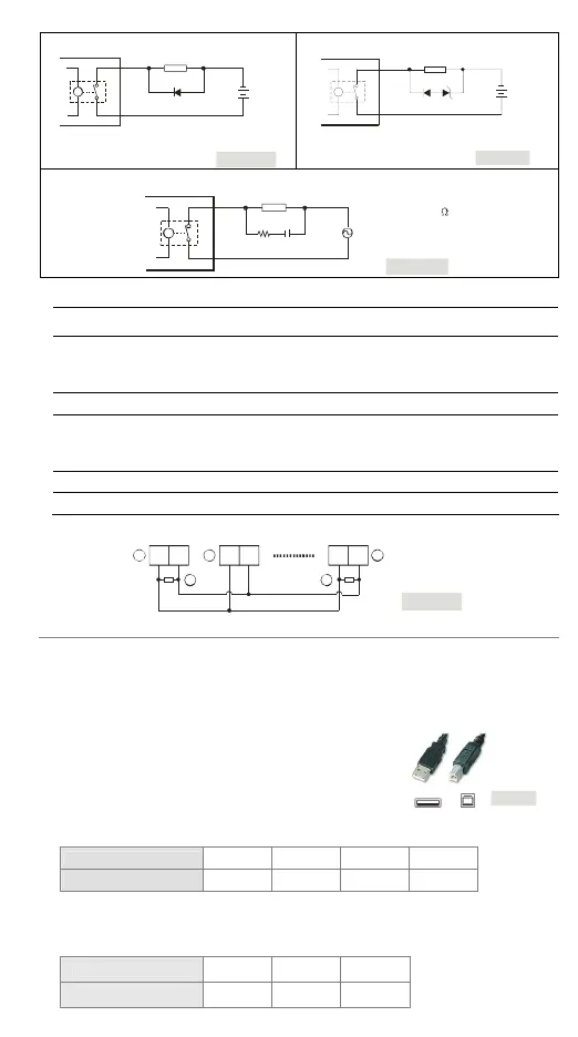
Communication Connection
TP04P may connect to a PC by using USB adaptor cable.
Please use an AM/BM USB adaptor cable.
Figure15
Battery’s Life
Temperature (°C) -20 0 20 60
Life (Year) 2.0 2.5 2.7 2.8
Precision of the Real Time Clock
(Second/Month)
Temperature (°C/°F) 0/32 25/77 55/131
Maximum error (Second) -117 52 -132
 Loading...