Chapter 2. Wiring | VFD-VJ
2-5
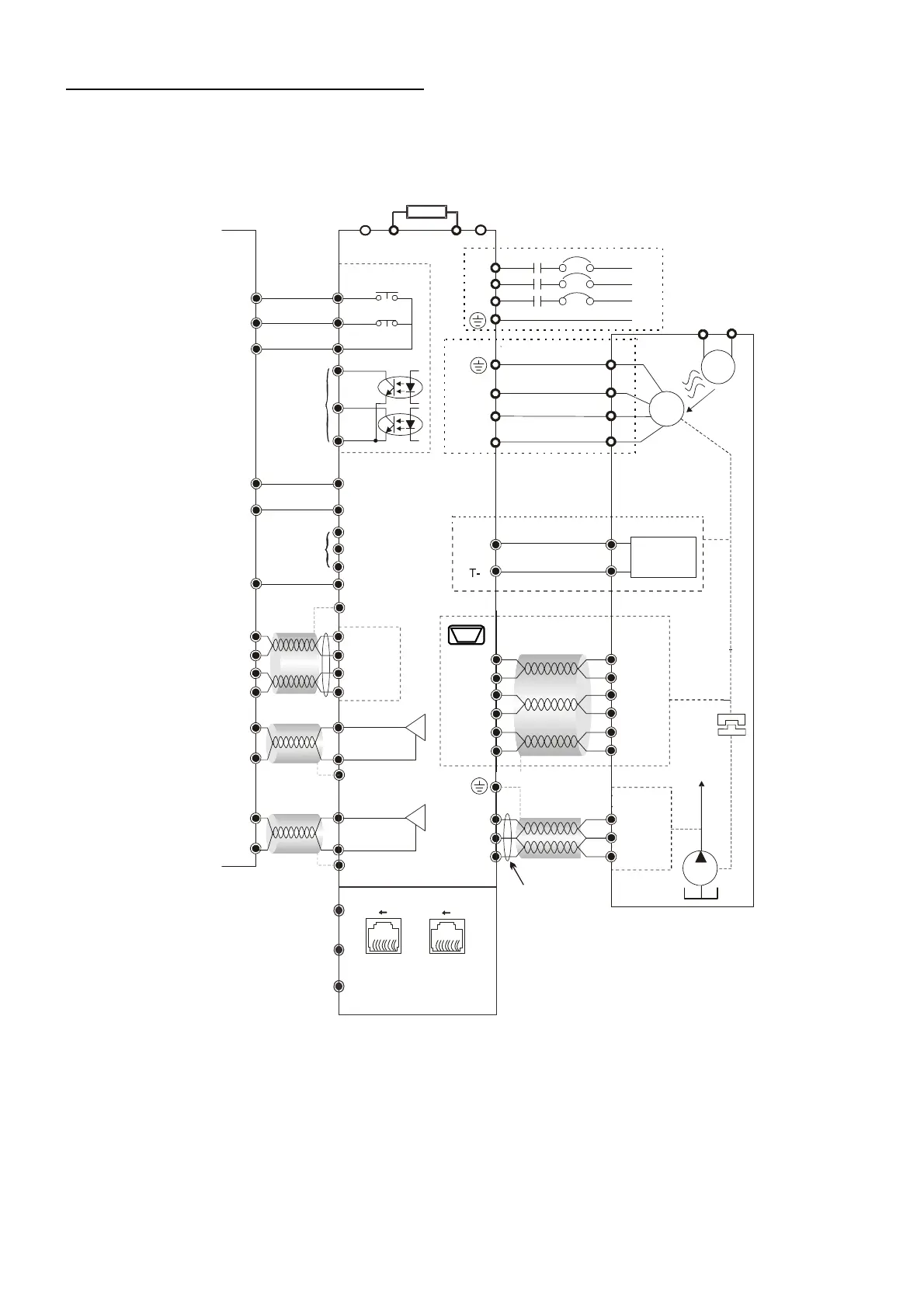
Wiring Diagram and Corresponding Models:
VFD110VL23A-J, VFD150VL23A-J, VFD185VL23A-J, VFD220VL23A-J, VFD110VL43C-J,
VFD150VL43C-J, VFD185VL43C-J, VFD220VL43C-J, VFD300VL43C-J, VFD370VL43C-J
RC
RA
RB
MO1
MO2
SON
RES
MI3
MI4
MI5
COM
PI
ACM
QI
ACM
L1
L2
L3
R
S
T
Reset
U
V
W
+V
-V
+24V
ACM
PS
AC
FAN
220V/ 380V
M
3~
U
V
W
MCM
AFM1
ACM
0~10 /2mA
V
DC
+ B12/
B2
T+
AFM2
ACM
-10 ~ +10
VV
DC DC
Feedback
Signal
KTY84/
PTC/ Temp.
Switch
R1
R2
S2
S4
S1
S3
14,16
13,15
5
4
7
9
Resolver
8181
SGND
SG+
SG-
Modbus/CAN
Pin1: CAN_H
Pin 2: CAN_L
Pin 4: SG-
Pin 5: SG+
Pin 3, 6: SGND
Pin 8: +15V
Pin 7: reserved
*1
*2
*3
PE
PE
Shielded
Cable
PE
Shielded
Cable
PE
PE
+1
-
Controller
Malfunction Indicators
Brake Resistor (must-have accessory)
Output Terminals
Ai
r
b
l
o
wi
n
g
d
i
r
e
c
ti
o
n
Enable
Oil Pump
Unused
Unused
Shielded
Cable
Pressure
Command
Flow
Command
Feedback
Signal
Shielded
Cable
Analog
Input
Terminals
Default setting:
Pressure Feedback
Only for output
frequency
Use a magnetic ring
Output
Pre ss ure Senso r
Temperature
Protections:

 Loading...