Chapter 12 Description of Parameter SettingsCP2000
12.1-03-17
Signal Loss Selection for Analog Input 4–20 mA
Default: 0
Settings 0: Disable
1: Continue operation at the last frequency
2: Decelerate to 0 Hz
3: Stop immediately and display ACE
Determines the response when the 4–20 mA signal is lost, when AVIc (Pr.03-28=2) or ACIc
(Pr.03-29=0).
When Pr.03-28 is not set to 2, the voltage input to AVI1 terminal is 0–10 V or 0–20 mA, and the
Pr.03-19 is invalid.
When Pr.03-29 is not set to 0, the voltage input to ACI terminal is 0–10 V, and the Pr.03-19 is
invalid.
When the setting is 1 or 2, the keypad displays the warning code “ANL”. It keeps blinking until the
ACI signal is recovered.
When the setting is 3, and the ACI terminal is disconnected, the keypad displays “ACE” error. It
keeps blinking until the connection is recovered and the error is reset.
When the motor drive stops, the warning condition does not continue to exist, so the warning
disappears.
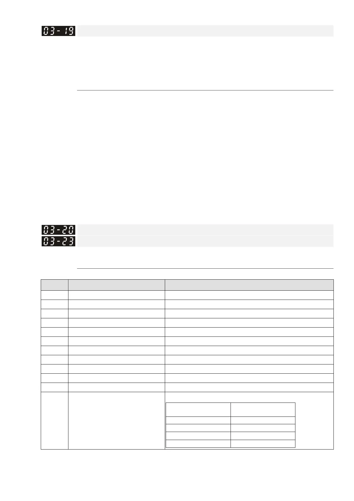
Multi-function Output 1 (AFM1)
Multi-function Output 2 (AFM2)
Default: 0
Settings 0–23
Function Chart
Settings Functions Descriptions
0 Output frequency (Hz) Maximum frequency Pr.01-00 is regarded as 100%.
1 Frequency command (Hz) Maximum frequency Pr.01-00 is regarded as 100%.
2 Motor speed (Hz) Maximum frequency Pr.01-00 is regarded as 100%
3 Output current (rms) (2.5 X rated current) is regarded as 100%
4 Output voltage (2 X rated voltage) is regarded as 100%
5 DC bus Voltage 450V (900V)=100%
6 Power factor -1.000–1.000=100%
7 Power Rated power is regarded as 100%
9 AVI1 percentage 0–10 V / 0–20 mA / 4–20 mA =0–100%
10 ACI percentage 4–20 mA / 0–10 V / 0–20 mA =0–100%
11 AVI2 percentage 0–10 V = 0–100%
20 CANopen analog output
CANopen communication analog output
Terminal
Corresponding
address
AFM1 2026-A1
AFM2 2026-A2
AO10 2026-AB
AO11 2026-AC