Chapter 12 Description of Parameter SettingsCP2000
12.1-06-20
Ripple of Input Phase Loss
Default:
30.0/ 60.0/ 75.0/ 90.0
Settings 230V series: 0.0–100.0 V
DC
460V series: 0.0–200.0 V
DC
575V series: 0.0–400.0 V
DC
690V series: 0.0–480.0 V
DC
When the DC bus ripple is higher than Pr.06-52, and continues for Pr.06-50 plus 30 seconds, the
drive triggers an OrP and acts according to the setting of Pr.06-53 to stop.
In the time period Pr.06-50 plus 30 seconds, if the DC bus ripple is lower than Pr.06-52, the OrP
protection counter restarts.
Treatment for the Detected Input Phase Loss (OrP)
Default: 0
Settings 0: Warn and ramp to stop
1: Warn and coast to stop
When the DC bus ripple voltage lasts for Pr.06-50 ripple time, the drive activates the Input Phase
Loss protection according to the Pr.06-53 settings:
DC bus ripple frequency ≤ 166 Hz
The amplitude is higher than Pr.06-52 setting [default 30 V (230V series), 60 V (460V
series)]. It starts to count time after 20 consecutive times.
When the following conditions continue,ORP occurs.
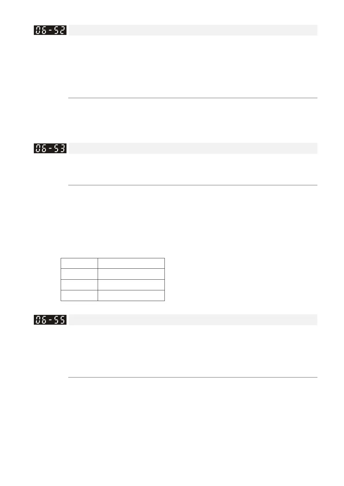
(I)% is rated current percentage
(I)% Actual seconds
50 432
75 225
120 60
When any condition is not satisfied, the ORP protect function is recalculated.
Derating Protection
Default: 0
Settings 0: Constant rated current and limit carrier wave by load current and
temperature
1: Constant carrier frequency and limit load current by setting carrier wave
2: Constant rated current (same as setting 0), but close current limit
The maximum output frequency and its corresponded carrier frequency lower limit under each
control mode:
VF, SVC: 599 Hz, 6K
FOC sensorless (IM): 300 Hz, 6K
FOC sensorless (PM): 500 Hz, 10K
Setting 0:
When the operating point is greater than the derating curve, the rated current is constant, and
carrier frequency (Fc) output by the drive decreases automatically according to the ambient