Chapter 16 PLC Function ApplicationsMS300
676
16-4-3 Overview of PLC ladder diagram editing
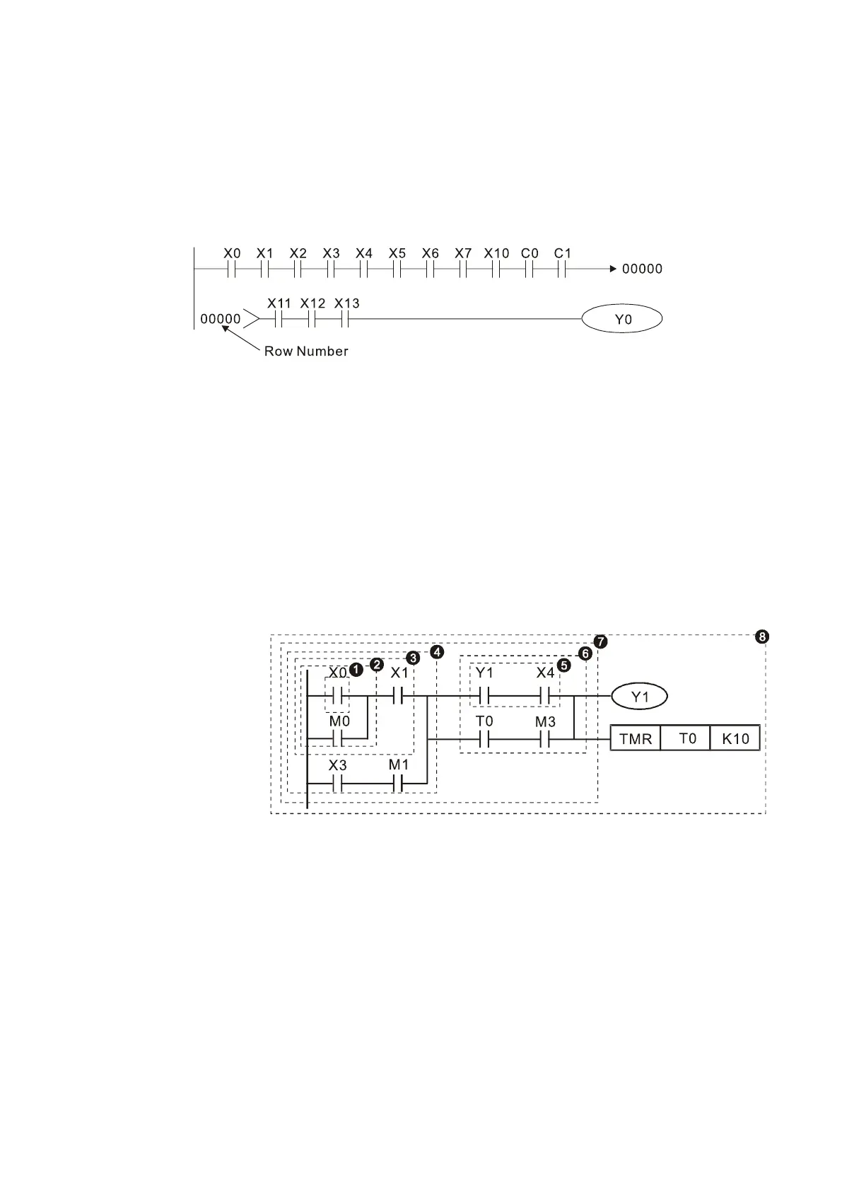
The program editing method in WPLSoft begins from the left busbar and proceeds to the right busbar
(the right busbar is not visible in WPLSoft). Continue to the next row after completing each row; there
are a maximum of 11 contacts on each row. If this is not sufficient, WPLSoft generates a continuous
line to indicate the continued connection, so that you can add more devices. A continuous series of
numbers is generated automatically and you can use identical input points repeatedly (as shown in
the following diagram).
Figure 16-27
The PLC scans a ladder diagram programs from the upper left corner to the lower right corner. The
coils and application command computing box are handled in the output, and in the ladder diagram
are placed on the farthest right of a rung. Taking the diagram below as an example, we can analyze
the procedural sequence of the ladder diagram. The number in the upper right corner gives the
sequential order.
 Loading...