Chapter 8 Option CardsC2000 Plus
8-49
Environment
Noise immunity
ESD (IEC 61800-5-1, IEC 61000-4-2)
EFT (IEC 61800-5-1, IEC 61000-4-4)
Surge Test (IEC 61800-5-1, IEC 61000-4-5)
Conducted Susceptibility Test (IEC 61800-5-1, IEC 61000-4-6)
Operation
-10°C
– 15°C (temperature), 90% (humidity)
Storage
-25°C
– 70°C (temperature), 95% (humidity)
Vibration / shock
immunity
International standard: IEC 61800-5-1, IEC 60068-2-6 / IEC 61800-5-1,
IEC 60068-2-27
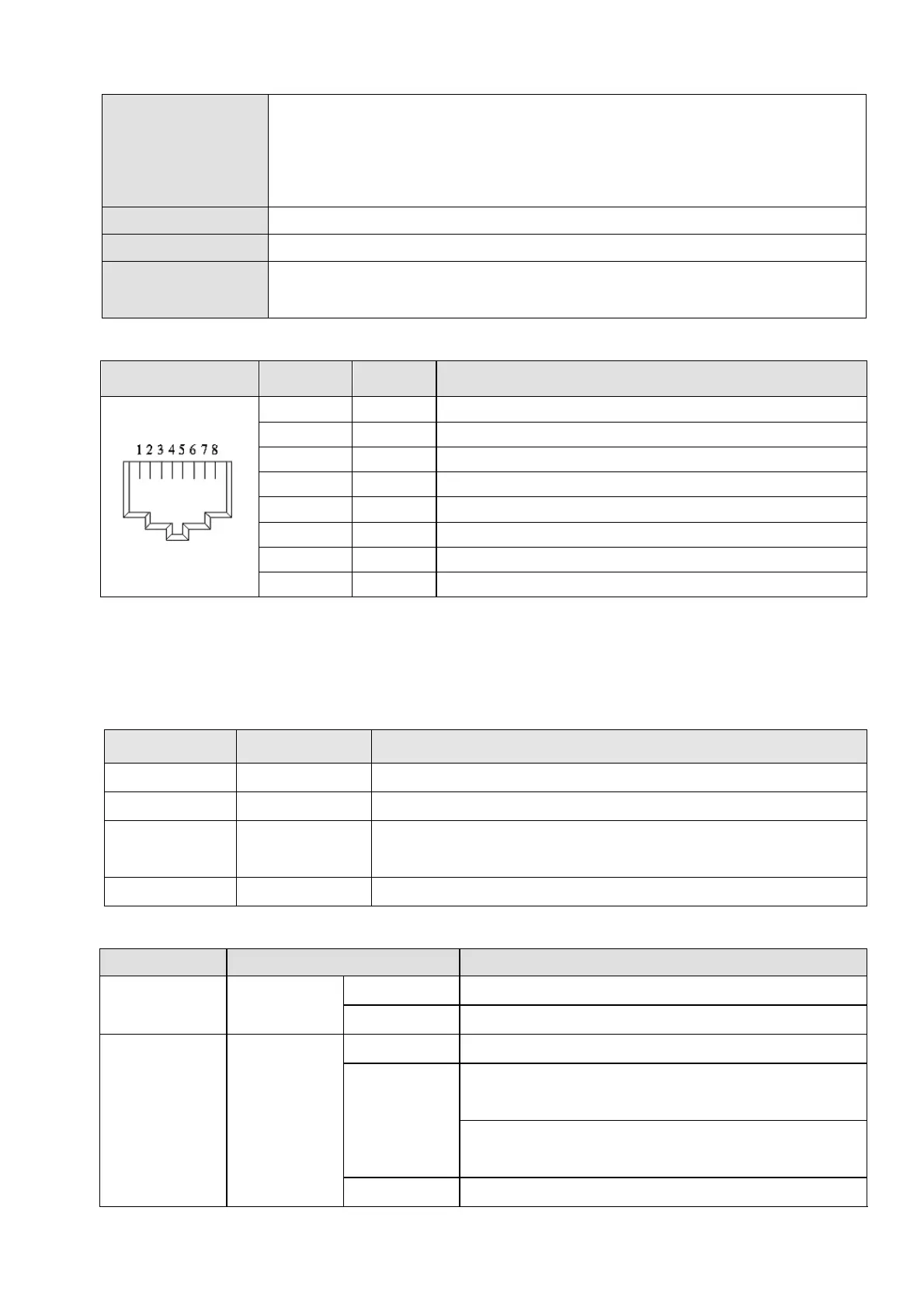
8-16-4 RJ45 PIN Definition
RJ45 PIN No. Signal Definition
1 Tx+ Positive pole for data transmission
2 Tx- Negative pole for data transmission
3 Rx+ Positive pole for data receiving
4 -- N / C
5 -- N / C
6 Rx- Negative pole for data receiving
7 -- N / C
8 -- N / C
8-16-5 Communication Parameters for C2000 Plus Connected to EtherCAT
When operating C2000 Plus via CMC-EC01, set the control and operation command as controlled
by communication card. When C2000 Plus connects to EtherCAT network, set up the communication
parameters according to the table below.
8-16-6 LED Indicator
LED Status Indication
POWER Green
ON
Power supply in normal status
OFF No power supply
LINK Green
ON
Normal operation
Flashes
Pre-operation (The light stays ON for 200 ms and then
goes OFF for 200 ms alternately)
Operate in safe mode (The light stays ON for 200 ms
and then goes OFF for 1000 ms alternately)
OFF Initial state
Parameters Set value (Dec) Explanation
00-20 8 The frequency command is controlled by communication card.
00-21 5 The operation command is controlled by communication card.
09-60 6
Identification: when CMC-EC01 is connected, Pr.09-60 will show
value 6 (EtherCAT Slave)
09-61 -- Version of communication card