EasyManuals Logo

Delta VFD2A8MS21ANSAA User Manual

Delta VFD2A8MS21ANSAA
805 pages
To Next Page IconTo Next Page
To Previous Page IconTo Previous Page
Page #347 background imageLoading...
Page #347 background image
Chapter 12 Descriptions of Parameter SettingsMS300
338
03-28
AVI Terminal Input Selection
Default: 0
Settings
0: 0–10 V (Pr.03-63–Pr.03-68 is valid)
3: -1010 V (Pr.03-69–Pr.03-74 are valid)
03-29
ACI Terminal Input Selection
Default: 0
Settings
0: 420 mA
1: 010 V
2: 020 mA
When you change the input mode, verify that the external terminal switch (ACI) position is
correct.
When you change the setting, proportion to the corresponding AVI and ACI will change to
default.
03-30
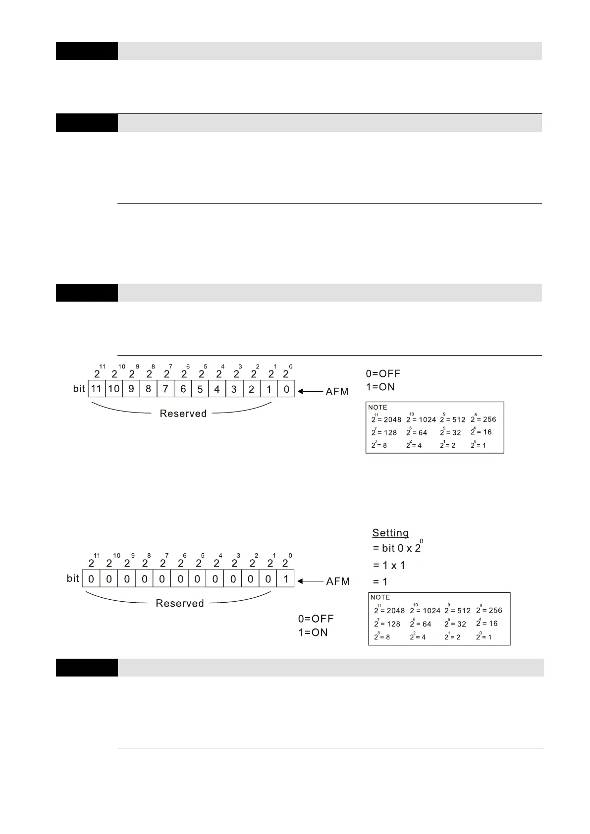
PLC Analog Output Terminal Status
Default: Read only
Settings
Monitor the status of the PLC analog output terminals
bit 0: AFM
Example:
When Pr.03-30 displays 0001 (hex) (that is, the value is 1 (decimal) and 1 (binary)), it means
that AFM is used by PLC.
03-31
AFM Output Selection
Default: 0
Settings
0: 010 V output
1: 020 mA output
2: 420 mA output

Table of Contents

Other manuals for Delta VFD2A8MS21ANSAA

Questions and Answers:

Question and Answer IconNeed help?

Do you have a question about the Delta VFD2A8MS21ANSAA and is the answer not in the manual?

Delta VFD2A8MS21ANSAA Specifications

General IconGeneral
BrandDelta
ModelVFD2A8MS21ANSAA
CategoryDC Drives
LanguageEnglish

Related product manuals