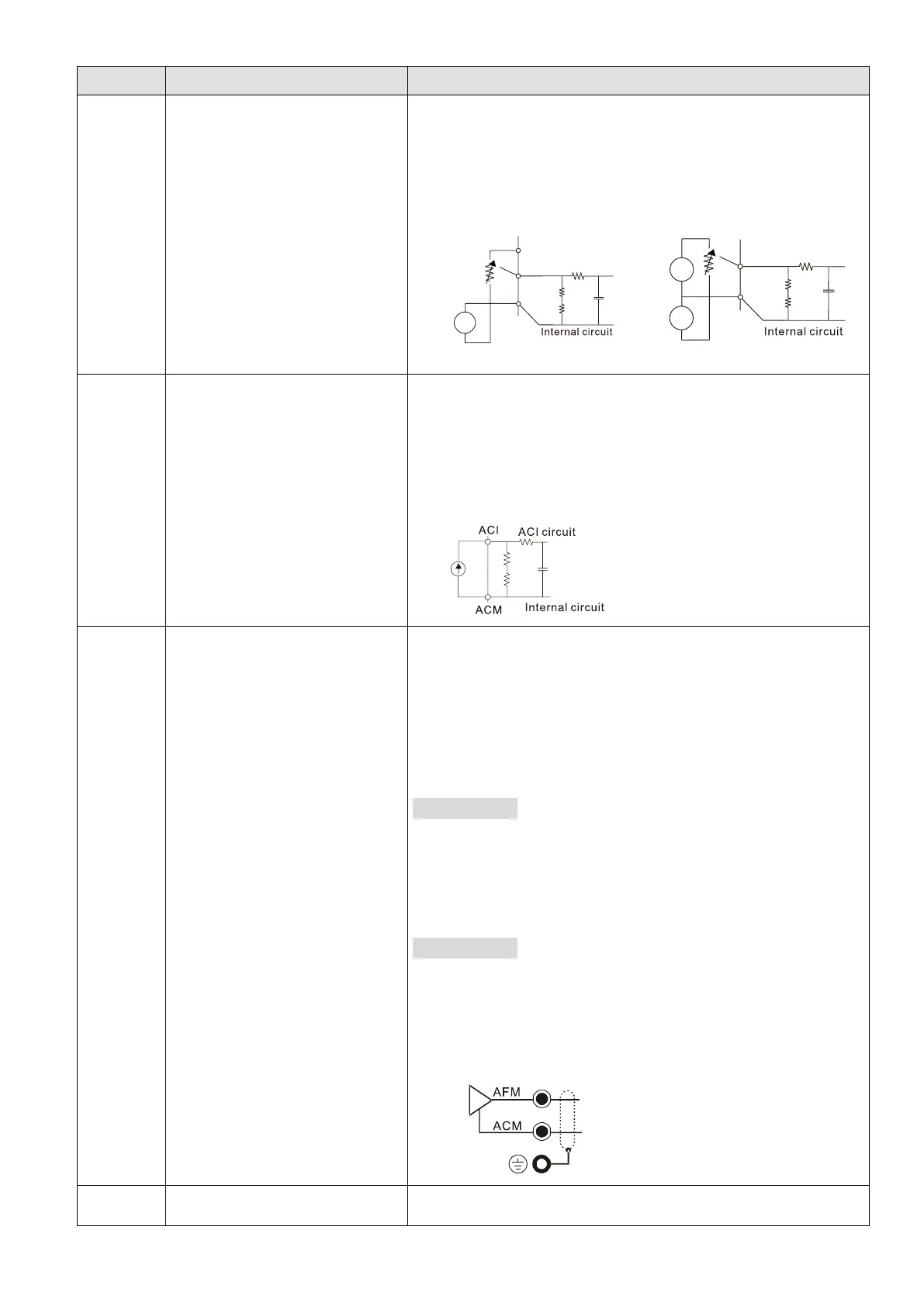
EasyManuals Logo

Delta VFD2A8MS21ANSAA User Manual

Delta VFD2A8MS21ANSAA
805 pages
To Next Page IconTo Next Page
To Previous Page IconTo Previous Page
Page #54 background imageLoading...
Page #54 background image
Chapter 6 Control TerminalsMS300
45
Terminals
Terminal Function
Description
AVI
Analog voltage frequency
command
Impedance: 20 kΩ
Range: 0–10 V / -1010 V = 0–Maximum Operation
Frequency (Pr.01-00)
Mode switching by setting Pr.03-28
AVI resolution = 11 bits (010 V) / 12 bits (-10–10 V)
Figure 6-11
Figure 6-12
ACI
Analog current frequency
command
Impedance: Current mode=250 Ω, Voltage mode=20
Range: 0–20 mA / 4–20 mA / 0–10 V = 0–Maximum
Operation Frequency (Pr.01-00)
Mode switching by setting Pr. 03-29
ACI resolution = 12 bits
Figure 6-13
AFM
Multi-function analog voltage
output
Switch: The AFM default is 010 V (voltage mode).
To switch to the current mode, follow the
instructions indicated on the inner side of the front
cover or refer to page 2 of Chapter 6 in the user
manual to switch AFM to the current mode position
(020 mA / 4–20 mA) and set Pr.03-31.
Voltage mode
Range: 0–10 V (Pr.03-31 = 0) corresponds to the maximum
operating range of the control target
Max. output current: 2 mA
Max. Load: 5 kΩ
Current mode
Range: 0–20 mA (Pr.03-31 = 1) / 420 mA (Pr.03-31 = 2)
corresponds to the maximum operating range of the
control target, maximum load 500 Ω
AFM resolution=10 bits
Figure 6-14
ACM
Analog Signal Common
Analog signal common terminal
+
-
+10V
AVI (-10V~+10V)
ACM
-10V
0V
+
-
+10V
AVI (-10V~+10V)
ACM
-10V
0V
+
-

Table of Contents

Other manuals for Delta VFD2A8MS21ANSAA

Questions and Answers:

Question and Answer IconNeed help?

Do you have a question about the Delta VFD2A8MS21ANSAA and is the answer not in the manual?

Delta VFD2A8MS21ANSAA Specifications

General IconGeneral
BrandDelta
ModelVFD2A8MS21ANSAA
CategoryDC Drives
LanguageEnglish

Related product manuals