EasyManua.ls Logo

Delta VFD2A8MS21ANSAA User Manual

Delta VFD2A8MS21ANSAA
805 pages
To Next Page IconTo Next Page
To Previous Page IconTo Previous Page
Page #652 background imageLoading...
Page #652 background image
Chapter 15 CANopen OverviewMS300
643
15-3-3 Using the Delta Standard (Old definition, only supports speed mode)
15-3-3-1 Various mode control method (following the Delta old standard)
If you want to use the Delta old standard to control the motor drive, follow these steps:
1. Wire the hardware (refer to Section 15-2 Wiring for CANopen).
2. Set the operation source: set Pr.00-21 to 3 for CANopen communication card control.
3. Set the frequency source: set Pr.00-20 to 6. Choose the source for the Frequency command
from the CANopen setting.
4. Set Delta Standard (Old definition, only supports speed mode) as the control mode: Pr.09-40
= 0 and Pr.09-30 = 0.
5. Set the CANopen station: set Pr.09-36; the range is among 1–127. When Pr.09-36 = 0, the
CANopen slave function is disabled. Note that if an error appears (station address error CAdE
or CANopen memory error CFrE) when you finish the station setting, set Pr.00-02 = 7 to reset.
6. Set the CANopen baud rate: set Pr.09-37 (CANBUS baud rate: 1 Mbps (0), 500 Kbps (1), 250
Kbps (2), 125 Kbps (3), 100 Kbps (4) and 50 Kbps (5))
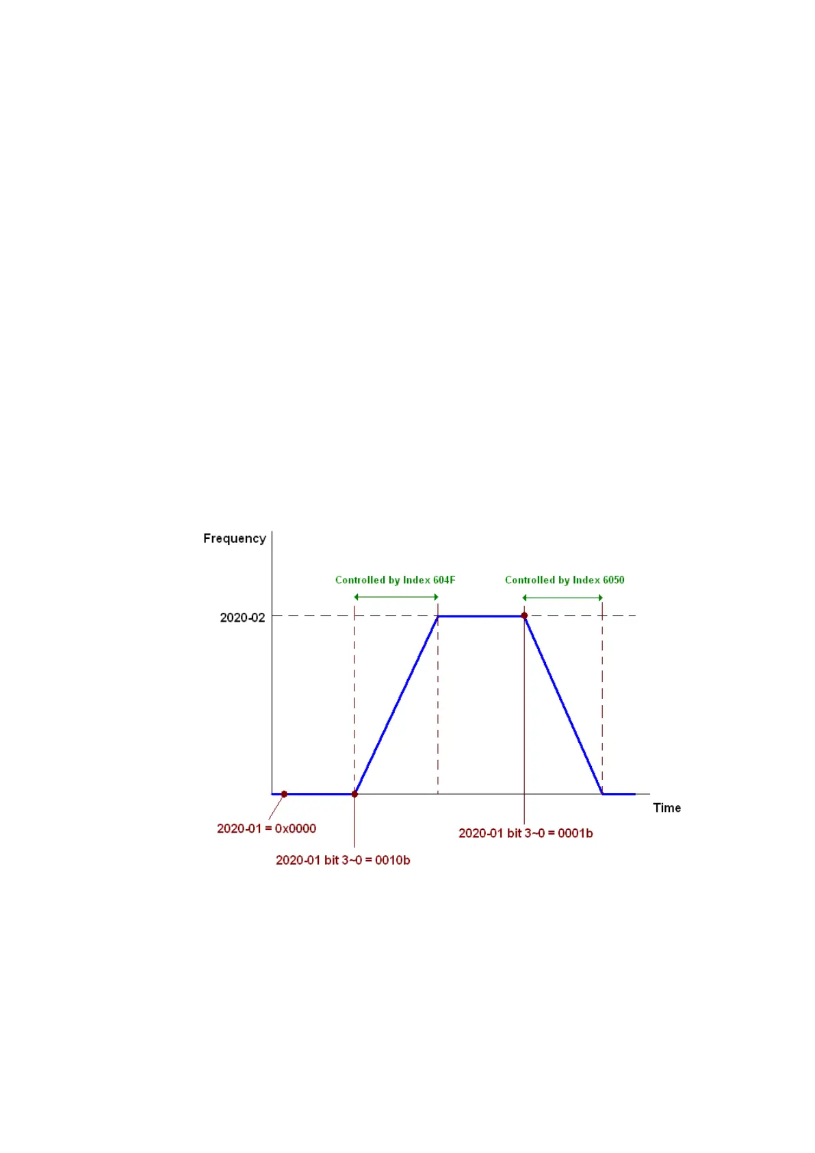
15-3-3-2 The control method under speed mode
1. Set the target frequency: set 2020-02, the unit is Hz, with 2 decimal places. For example,
1000 is 10.00 Hz.
2. Operation control: set 2020-01 = 0002H for running, and set 2020-01 = 0001H for stopping.

Table of Contents

Other manuals for Delta VFD2A8MS21ANSAA

Questions and Answers:

Delta VFD2A8MS21ANSAA Specifications

General IconGeneral
Protection LevelIP20
Control MethodV/F Control, Sensorless Vector Control
Frequency Range0.1-400Hz
Protection FeaturesOver-voltage, Over-current, Overload, Overheat, Low-voltage, Ground Fault, Short Circuit
Cooling MethodFan Cooling
Operating Temperature-10°C to 50°C
Storage Temperature-20°C to 60°C
Altitude1000m

Summary

Introduction

Important points regarding ground connection

Key safety regulations and correct/incorrect methods for grounding the motor drive and equipment.

Installation

3-1 Mounting Clearance

Specifies minimum required clearances (A, B, C) for single drive, side-by-side, and zero stack installations based on ambient temperature.

3-2 Airflow and Power Dissipation

Provides airflow rates and power dissipation values for various AC motor drives across different frames (A, B, C, D, E, F).

Wiring

4-1 System Wiring Diagram

Illustrates the system wiring diagram for power input, NFB/fuse, electromagnetic contactor, AC/DC reactors, and EMC filter.

4-2 Wiring

Details on input wiring for single-phase/three-phase power and wiring precautions for power and control terminals.

Main Circuit Terminals

5-1 Main Circuit Diagram

Provides a diagram of the main circuit terminals including R/L1, S/L2, T/L3, U/T1, V/T2, W/T3, DC-/DC+/+1, +2/B1, B2, and ground connection.

Control Terminals

6-1 Control Terminal Specifications

Details wiring specifications for Relay and Control terminals, including stripping length, wire gauge, and tightening torque.

Optional Accessories

7-1 Brake Resistors and Brake Units Used in AC Motor Drives

Lists brake resistors and brake units suitable for AC motor drives, including part numbers, specifications, and torque values.

7-14 Digital Keypad - KPC-CC01

Describes the KPC-CC01 digital keypad, its communication interface, protocol, installation method, and function descriptions.

Specifications

Digital Keypad

10-2 Keypad Operation Process

Details the operational processes for the keypad, including main page selection, setting parameters, shifting data, and PLC settings.

Summary of Parameter Settings

06 Protection Parameters (1)

Details protection parameters including low voltage level, over-voltage stall prevention, over-current stall prevention, and over-torque detection.

09 Communication Parameters

Summarizes communication parameters such as address, transmission speed, fault treatment, time-out detection, protocol, and block transfers.

14 Protection Parameters (2)

Lists protection parameters for output frequency, DC bus voltage, output current, and IGBT temperature malfunctions.

Descriptions of Parameter Settings

Warning Codes

Summary of Warning Codes

Lists all warning codes with their ID, display on LCD, name, description, and recommended error resolution.

Fault Codes

Summary of Fault Codes

Provides a comprehensive list of fault codes, including ID, display on LCD, fault name, fault descriptions, and corrective actions.

CANopen Overview

15-2 Wiring for CANopen

Provides instructions for CANopen wiring using an external communication card CMM-COP01 and RJ45 cable with terminating resistors.

PLC Function Applications

Safe Torque Off Function

17-3 Wiring Diagram

Provides wiring diagrams for the safe control loop, including internal circuit and STO wiring.

17-7 Error Code and Troubleshooting Instructions

Explains error codes related to STO/STL functions and provides troubleshooting instructions based on keypad display.

Appendix A. Modbus Protocol

Related product manuals