Chapter 1. Description of Hybrid Servo Drives | VFD-VJ
1-13
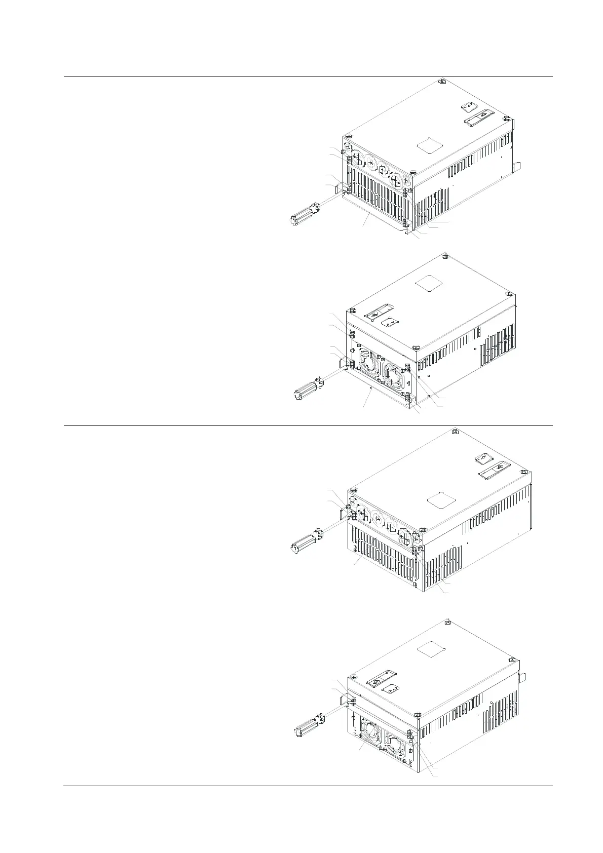
Flange Mounting
Step 1:
Please take out the 16 screws
(8 screws for each top and bottom side
of the drive) and remove the fixed
plate 1 and fixed plate 2 as shown in
the following figures.
3
4
1
2
7
8
5
6
fixed plate 1
1
2
5
6
3
4
7
8
fixed pl ate 2
Step 2:
Place the 8 screws back in to secure
the fixed plate 1 and fixed plate 2 (as
shown in the following figures) with the
following torque.
Frame C: 14-17kg-cm [12.2-14.8 lb-in]
Frame D: 20-25kg-cm [17.4-21.lb-in]
1
2
3
4
fixed plate 1
1
2
3
4
fixed plate 2
 Loading...
