-
-
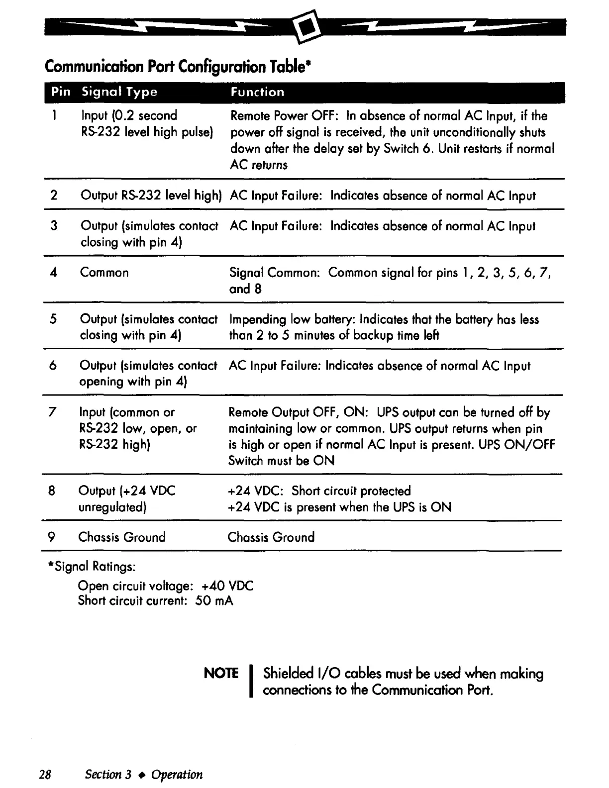
Communication
Port
Configuration
Table•
Pin
Signal
Type
Function
1 Input (0 .2 second
RS-232
level high
pulse)
Remote
Power OFF:
In
absence
of
normal AC Input,
if
the
power off signal
is
received,
the
unit unconditionally
shuts
down ofter
the
delay
set
by Switch 6. Unit
restarts
if normal
AC returns
2 Output
RS-232
level high) AC Input Failure: Indicates absence of normal AC Input
3 Output (simulates contact AC Input Failure: Indicates absence of normal AC Input
closing with pin 4)
4 Common
Signal Common: Common signal for pins 1, 2, 3, 5, 6, 7,
and 8
5 Output (simulates contact Impending
low
battery: Indicates that
the
battery
has
less
closing with pin 4)
than
2
to
5 minutes
of
backup
time
left
6 Output (simulates contact AC Input Failure: Indicates absence
of
normal AC Input
opening with pin 4)
7 Input (common or
RS-232
low, open, or
RS-232
high)
8 Output (+24 VDC
unregulated)
9
Chassis
Ground
*Signal Ratings:
Remote
Output
OFF,
ON:
UPS
output con
be
turned off by
maintaining low or common.
UPS
output
returns
when pin
is
high or open
if
normal AC Input
is
present.
UPS
ON/OFF
Switch
must
be
ON
+24
VDC: Short circuit protected
+
24
VDC
is
present when
the
UPS
is
ON
Chassis
Ground
Open circuit voltage: +40
VDC
Short circuit current:
50
mA
28
Section
3 •
Operation
NOTE
I
Shielded
1/0
cables
must
be
used
when
making
connections
to
the
Communication
Port.