DEMA ATLAS 844P
™
SERIES
LAUNDRY CONTROL
I-907 Page 7 of 17
Rev. C-33371
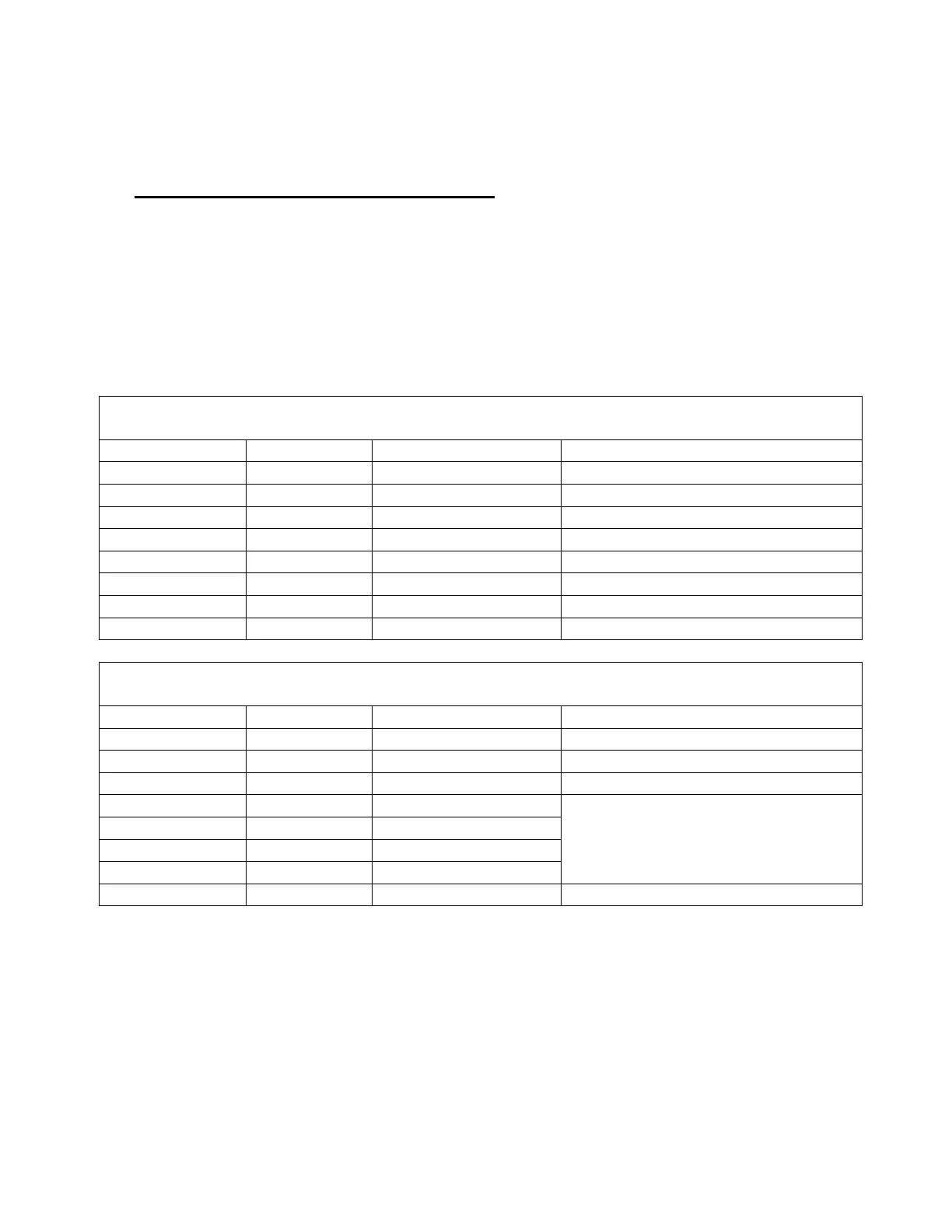
4. Wire the STU to the laundry machine. The hookup configuration will depend on
which of the operational modes the DEMA 844P Laundry System will be used. The
following two tables show the wiring configurations for the input signals to the
STU. The first is for normal and relay modes and the second is for sequence mode.
Verify the mode that will be used and wire the STU according to the appropriate
table below using the leads that are coming out of the left side of the STU. Keep in
mind that trigger sources should be at least 24VAC but no higher than 240VAC
50/60Hz.
STU Wiring Configuration (For Formula Select Mode or Relay Mode)
Trigger Input Line (signal) Common Function of Trigger Input
1 Black White/Black Stripe Signal Pump 1
2 Brown White/Brown Stripe Signal Pump 2
3 Red White/Red Stripe Signal Pump 3
4 Orange White/Orange Stripe Signal Pump 4
5 Yellow White/Yellow Stripe Signal Pump 5
6 Green White/Green Stripe Signal Pump 6
7 Blue White/Blue Stripe Signal Flush (optional)
8 Purple White/Purple Stripe Auto Formula Select
STU Wiring Configuration (For Sequence Mode)
Trigger Input Line (signal) Common Function of Trigger Input
1 Black White/Black Stripe Event Trigger
2 Brown White/Brown Stripe Event Trigger
3 Red White/Red Stripe
Reset (optional) example, door switch
4 Orange White/Orange Stripe
5 Yellow White/Yellow Stripe
6 Green White/Green Stripe
7 Blue White/Blue Stripe
Not Used
8 Purple White/Purple Stripe Auto Formula Select
 Loading...