25
3.25 Unit Terminal Blocks
Sockets make the electrical connection by locking to the plugs when the internal unit is drawn
into the case. All sockets are made of inflammable material.
3.26 Internal Unit Tracks
High-endurance internal unit tracks provide robust draw-in and draw-out operation of the
internal unit.
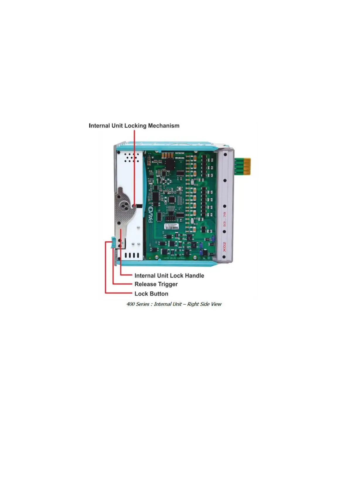
3.27 Internal Unit Locking Mechanism
As a subsystem of the patented DDS (DEMA Draw out System) technology, internal unit
locking mechanism provides locking and drawing out of the internal unit with ease. Locking
ensures safe electrical contacts.
3.28 Internal Unit Lock Handle and Release Trigger
The internal unit lock handle is released by the release trigger - that enables the drawing out
of the internal unit by rotating the handle in upwards direction.
3.29 Lock Button
Lock button is used for locking the handle and the internal unit after the internal unit is drawn
completely into the case. Before drawing the internal unit in, lock handle must be positioned
parallel to the ground.
 Loading...