Do you have a question about the DEMA DPM 400 D and is the answer not in the manual?
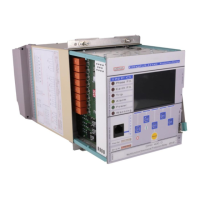
Describes the relay's stainless steel case, PVC coating, terminal blocks, and earthing provisions.
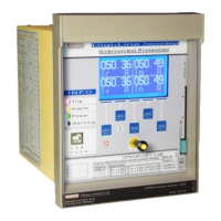
Details the function and behavior of Phase Fault, Earth Fault, Trip, and Alarm LEDs.
Covers Power/Error LEDs, Ethernet port, and IP52 front cover.
Describes the TFT display, multifunctional/reset buttons, and the internal unit lock mechanism.
Explains device labels, earthing screws, terminal blocks, and special case coating.
Details the circuit diagram, internal unit design, and mounting tracks for the relay.
Covers case earthing continuity and the Faraday cage for internal component protection.
Describes terminal blocks, unit tracks, locking mechanisms, and handle/trigger functions.
Details cover mounting screws, terminal plugs, lock pivots, and mounting holes.
Displays device-specific data like serial number, firmware version, and hardware details.
Provides real-time monitoring of voltage, current, power, and frequency measurements.
Allows configuration and adjustment of various protection functions and their parameters.
Manages device language, date-time, display settings, and other system configurations.
Enables field installation setup, phase rotation, blocking modes, and communication settings.
| Amperage | 10A |
|---|---|
| Contact Type | SPDT |
| Rated Current | 10A |
| Contact Configuration | 1 Form C (SPDT) |
| Mechanical Life | 10, 000, 000 operations |
| Protection Degree | IP40 |
| Coil Voltage | 24V DC |
| Electrical Life | 100, 000 operations |
| Voltage | 250V AC/30V DC |
| Rated Voltage | 250V AC/30V DC |