EasyManuals Logo

DEMA DPM 400 D User Manual

DEMA DPM 400 D
118 pages
To Next Page IconTo Next Page
To Previous Page IconTo Previous Page
Page #26 background imageLoading...
Page #26 background image
26
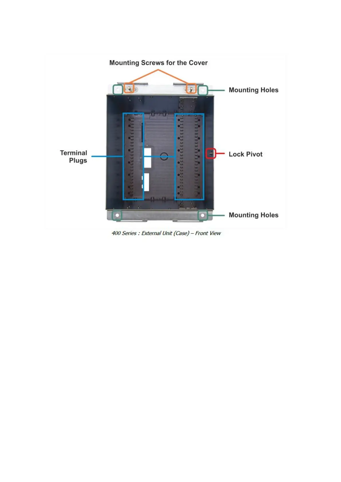
3.30 Mounting Screws for the Cover
The cover is mounted onto the case via these screws. Screws are permanently fixed on the
case.
3.31 Terminal Plugs
Plugs make the electrical connection by locking to the sockets when the internal unit is drawn
into the case.
3.32 Lock Pivot
Internal unit locking mechanism locks to this pivot, providing mechanical and contacting
stability.
3.33 Mounting Holes
The relay case is mounted on the panel or rack from these mounting holes. Connection
elements necessary for mounting the case is supplied within the product box.

Table of Contents

Questions and Answers:

Question and Answer IconNeed help?

Do you have a question about the DEMA DPM 400 D and is the answer not in the manual?

DEMA DPM 400 D Specifications

General IconGeneral
BrandDEMA
ModelDPM 400 D
CategoryRelays
LanguageEnglish

Related product manuals