60
heat up and cause faults in a short time is solved by thermal overload protection functions in
modern systems.
Thermal Overload Protecions are shown in IEC 60617 Standards with I
>-A; in IEC 61850
Standards with PH_PTTR_A; in IEEE / ANSI Standards with 49-A.
Thermal Overload Protection Function Symbols
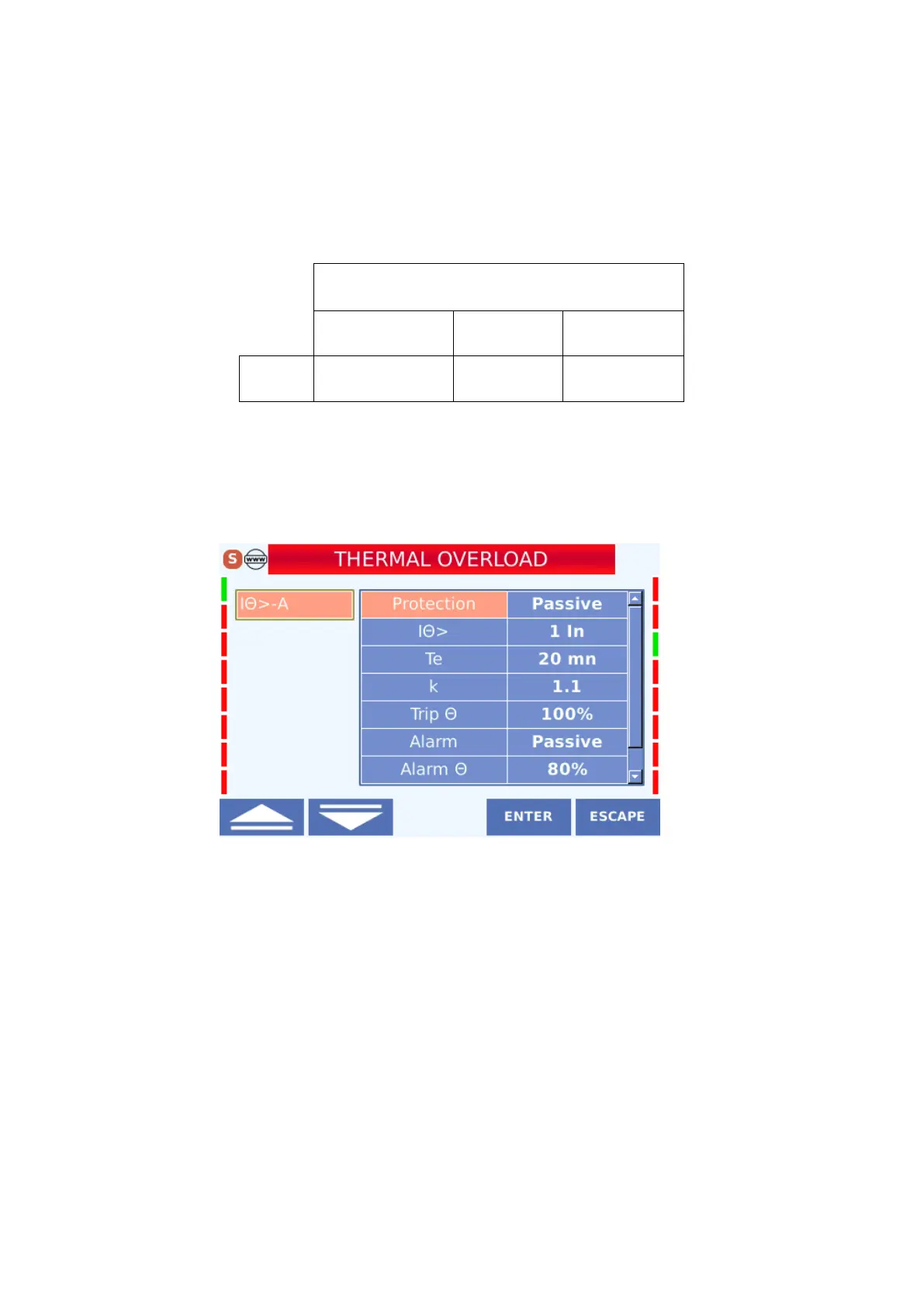
The menu view is as follows.
The settings that can be made in the menu are described below.
4.3.2.3.1 Protection
activated in the active state and disabled in the passive state.
4.3.2.3.2 I
Θ
>
The thermal protection shows the ratio of the nominal current of the device to the I
n
current
transformer primary nominal current and is called the thermal protection set current. This
value, for example, when thermal protection of measured 1600 kVA (34.5 / 0.4) kV power